Scans
Perhaps the most used type of macro is the scan macros. In general terms, we call scan to a macro that moves one or more motors and acquires data along the path of the motor(s).
Note
Sardana provides a Scan Framework for developing scan macros so that the scan macros behave in a consistent way. Unless otherwise specified, the following discussion applies to scan macros based on such framework.
The various scan macros mostly differ in how many motors are moved and the definition of their paths.
Typically, the selection of which data is going to be acquired depends on the active measurement group and is not fixed by the macro itself (although there is no limitation in this sense).
Depending on whether the motors are stopped before acquiring the data or not, we can classify the scan macros in step scans or continuous scans, respectively.
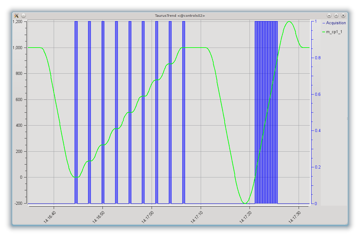
Trend plot showing a step scan (ascan m_cp1_1 0 1000 8 .5)
followed by a continuous scan (ascanc m_cp1_1 0 1000 .5).
The line corresponds to the motor position and the blue shaded areas
correspond to the intervals in which the data acquisition took place.
Step scans
In a step scan, the motors are moved to given points, and once they reach each point they stop. Then, one or more channels are acquired for a certain amount of time, and only when the data acquisition is finished, the motors proceed to the next point.
In this way, the position associated to a data readout is well known and does not change during the acquisition time.
Some examples of step scan macros are:
ascan,
a2scan, ...
dscan,
d2scan, ...
mesh.
Continuous scans
In a continuous scan, the motors are not stopped for acquisition, which therefore takes place while the motors are moving. The most common reason for using this type of scan is optimizing the acquisition time by not having to wait for motors to accelerate and decelerate between acquisitions.
Note
The synchronization of movement and acquisition can be done via hardware or via software. Currently Sardana only provides an interface for software-synchronized continuous scans. An API abstracting the specificities of hardware-synchronized systems is being implemented too but it is not yet available for production.
The (software-synchronized) continuous scans introduce some constraints and issues that should be considered.
- If a continuous scan involves moving more than one motor simultaneously
(as it is done, e.g. in
a2scan), then the movements of the motors should be synchronized so that they all start their path at the same time and finish it at the same time. - If motors do not maintain a constant velocity along the path of their movement, the trajectories followed when using more than one motor may not be linear.
- While in step scans it is possible to scan two pseudo-motors that access the same physical motors (e.g. the gap and offset of a slit, being both pseudo-motors accessing the same physical motors attached to each blade of the slit), in a continuous scan the motions cannot be decoupled in a synchronized way.
- In order to optimize the acquisition time, Sardana attempts to perform as many acquisitions as allowed during the scan time. Due to the uncertainty in the delay times involved, it is not possible to know beforehand how many acquisitions will be completed. In other words, the number of acquired points along a continuous scan is not fixed (but it is guaranteed to be as large as possible).
- Backslash correction is incompatible with continuous scans, so you should keep in mind that continuous scans should only be done in the backslash-free direction of the motor (typically, by convention the positive one for a physical motor).
In order to address the first two issues, the scan framework attempts the following:
- If the motors support changing their velocity, Sardana will adjust the velocities of the motors so that they all start and finish the required path simultaneously. For motors that specify a range of allowed velocities, this range will be used (for motors that do not specify a maximum allowed velocity, the current “top velocity” will be assumed to be the maximum)
- For motors that can maintain a constant velocity after an acceleration phase (this is the case for most physical motors), Sardana will transparently extend the user-given path both at the beginning and the end in order to allow for the motors to move at constant velocity along all the user defined path (i.e., the motors are allowed time and room to accelerate before reaching the start of the path and to decelerate after the end of the nominal path selected by the user)
These two actions can be seen in the following plot of the positions of the two
motors involved in a a2scanc.
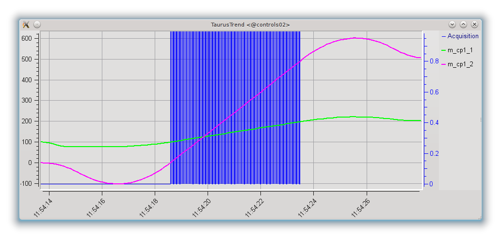
Trend plot showing a two-motor continuous scan
(a2scanc m_cp1_1 100 200 m_cp1_2 0 500 .1).
The lines correspond to the motor positions and the blue shaded areas correspond to the intervals in
which the data acquisition took place.
Both motors are capable of same velocity and acceleration, but since the required scan path for m_cp1_1 is shorter than that for m_cp1_2, its top velocity has been adjusted (gentler slope for m_cp1_1) so that both motors go through the user-requested start and stop positions simultaneously.
The same figure also shows how the paths for both motors have been automatically (and transparently, for the user) extended to guarantee that the user defined path is followed at constant velocity and that the data acquisition takes place also while the motors are running at constant velocity.
Some examples of continuous scan macros are:
ascanc,
a2scanc, ...
dscanc,
d2scanc, ...
meshc.
See also
For more information about the implementation details of the scan macros in Sardana, see scan framework