Device Pool Tango API
Warning
Device Pool chapter is out of date. Some parts of it are not valid and may create confusions e.g. “Specifying the motor controller features”.
Todo
Update this chapter and distribute its contents logically around the documentation.
Introduction
This paper describes what could be the implementation of the Sardana device pool. This work is based on Jorg’s paper called “Reordered SPEC”. It is not at all a final version of this device pool. It is rather a first approach to define this pool more precisely and to help defining its features and the way it could be implemented.
Overall pool design
The pool could be seen as a kind of intelligent Tango device container to control the experiment hardware. In a first approach, it requires that the hardware to be controlled is connected to the control computer or to external crate(s) connected to the control computer using bus coupler. It has two basic features which are:
- Hardware access using dynamically created/deleted Tango devices according to the experiment needs
- Management of some very common and well defined action regularly done on a beam line (scanning, motor position archiving….)
To achieve these two goals and to provide the user with a way to control its behavior, it is implemented as a Tango class with commands and attributes like any other Tango class.
Hardware access
Core hardware access
Most of the times, it is possible to define a list of very common devices found in most of the experiments, a list of communication link used between the experiment hardware and the control computer(s) and some of the most commonly used protocol used on these communication links. Devices commonly used to drive an experiment are:
- Motor
- Group of motor
- Pseudo motor
- Counter/Timer
- Multi Channel Analyzer
- CCD cameras
- And some other that I don’t know
Communication link used to drive experiment devices are:
- Serial line
- GPIB
- Socket
- And some other that I don’t know (USB????)
Protocol used on the communication links are:
- Modbus
- Ans some other that I don’t know
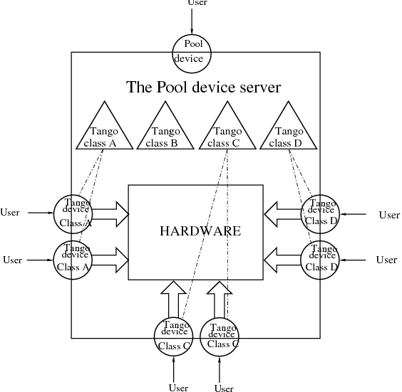
Each of the controlled hardware (one motor, one pseudo-motor, one serial line device,…) will be driven by independent Tango classes. The pool device server will embed all these Tango classes together (statically linked). The pool Tango device is the “container interface” and allows the user to create/delete classical Tango devices which are instances of these embedded classes. This is summarized in the following drawing.
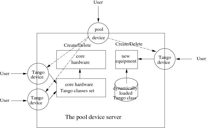
Therefore, the three main actions to control a new equipment using the pool will be (assuming the equipment is connected to the control computer via a serial line):
- Create the serial line Tango device with one of the Pool device command assigning it a name like “MyNewEquipment”.
- Connect to this newly created Tango device using its assigned name
- Send order or write/read data to/from the new equipment using for instance the WriteRead command of the serial line Tango device
When the experiment does not need this new equipment any more, the user can delete the serial line Tango device with another pool device command. Note that most of the time, creating Tango device means defining some device configuration parameters (Property in Tango language). The Tango wizard will be used to retrieve which properties have to be defined and will allow the user to set them on the fly. This means that all the Tango classes embedded within the Pool must have their wizard initialized.
Extending pool features
From time to time, it could be useful to extend the list of Tango classes known by the device pool in case a new kind of equipment (not using the core hardware access) is added to the experiment. Starting with Tango 5.5 (and the associated Pogo), each Tango class has a method which allow the class to be dynamically loaded into a running process. This feature will be used to extend the pool feature. It has to be checked that it is possible for Tango Python class.
To achieve this feature, the pool Tango device will have commands to
Load a Tango class. This command will dynamically add two other commands and one attribute to the pool device Tango interface. These commands and the attribute are:
- Command: Create a device of the newly loaded class
- Command: Delete a device of the newly loaded class
- Attribute: Get the list of Tango devices instances of the newly created class
Unload a Tango class
Reload a Tango class
Global actions
The following common actions regularly done on a beam line experiment will be done by the pool device server:
- Evaluating user constraint(s) before moving motor(s)
- Scanning
- Saving experiment data
- Experiment management
- Archiving motor positions
Sardana core hardware access
The Sardana Motor management
The user motor interface
The motor interface is a first approach of what could be a complete motor interface. It is statically linked with the Pool device server and supports several attributes and commands. It is implemented in C++ and used a set of the so-called “controller” methods. The motor interface is always the same whatever the hardware is. This is the rule of the “controller” to access the hardware using the communication link supported by the motor controller hardware (network link, serial line…).
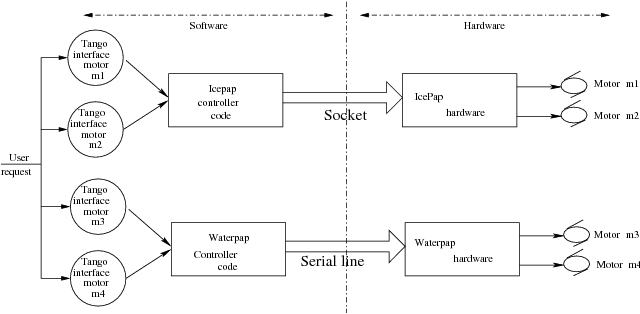
The controller code has a well-defined interface and can be written using Python or C++. In both cases, it will be dynamically loaded into the pool device server process.
The states
The motor interface knows five states which are ON, MOVING, ALARM, FAULT and UNKNOWN. A motor device is in MOVING state when it is moving! It is in ALARM state when it has reached one of the limit switches and is in FAULT if its controller software is not available (impossible to load it) or if a fault is reported from the hardware controller. The motor is in the UNKNOWN state if an exception occurs during the communication between the pool and the hardware controller. When the motor is in ALARM state, its status will indicate which limit switches is active.
The commands
The motor interface supports 3 commands on top of the Tango classical Init, State and Status commands. These commands are summarized in the following table:
| Command name | Input data type | Output data type |
|---|---|---|
| Abort | void | void |
| SetPosition | Tango::DevDouble | void |
| SaveConfig | void | void |
- Abort : It aborts a running motion. This command does not have input or output argument.
- SetPosition : Loads a position into controller. It has one input argument which is the new position value (a double). It is allowed only in the ON or ALARM states. The unit used for the command input value is the physical unit: millimeters or milli-radians. It is always an absolute position.
- SaveConfig : Write some of the motor parameters in database. Today, it writes the motor acceleration, deceleration, base_rate and velocity into database as motor device properties. It is allowed only in the ON or ALARM states
The classical Tango Init command destroys the motor and re-create it.
The attributes
The motor interface supports several attributes which are summarized in the following table:
| Name | Data type | Data format | Writable | Memorized | Ope/Expert |
|---|---|---|---|---|---|
| Position | Tango::DevDouble | Scalar | R/W | No * | Ope |
| DialPosition | Tango::DevDouble | Scalar | R | No | Exp |
| Offset | Tango::DevDouble | Scalar | R/W | Yes | Exp |
| Acceleration | Tango::DevDouble | Scalar | R/W | No | Exp |
| Base_rate | Tango::DevDouble | Scalar | R/W | No | Exp |
| Deceleration | Tango::DevDouble | Scalar | R/W | No | Exp |
| Velocity | Tango::DevDouble | Scalar | R/W | No | Exp |
| Limit_Switches | Tango::DevBoolean | Spectrum | R | No | Exp |
| SimulationMode | Tango::DevBoolean | Scalar | R | No | Exp |
| Step_per_unit | Tango::DevDouble | Scalar | R/W | Yes | Exp |
| Backlash | Tango::DevLong | Scalar | R/W | Yes | Exp |
Position : This is read-write scalar double attribute. With the classical Tango min and max_value attribute properties, it is easy to define authorized limit for this attribute. See the definition of the DialPosition and Offset attributes to get a precise definition of the meaning of this attribute. It is not allowed to read or write this attribute when the motor is in FAULT or UNKNOWN state. It is also not possible to write this attribute when the motor is already MOVING. The unit used for this attribute is the physical unit: millimeters or milli-radian. It is always an absolute position. The value of this attribute is memorized in the Tango database but not by the default Tango system memorization. See chapter XXX: Unknown inset LatexCommand ref{sub:Archiving-motor-position}: for details about motor position archiving.
DialPosition : This attribute is the motor dial position. The following formula links together the Position, DialPosition, Sign and Offset attributes:
Position = Sign * DialPosition + Offset
This allows to have the motor position centered around any position defined by the Offset attribute (classically the X ray beam position). It is a read only attribute. To set the motor position, the user has to use the Position attribute. It is not allowed to read this attribute when the motor is in FAULT or UNKNOWN mode. The unit used for this attribute is the physical unit: millimeters or milli-radian. It is also always an absolute position.
Offset : The offset to be applied in the motor position computation. By default set to 0. It is a memorized attribute. It is not allowed to read or write this attribute when the motor is in FAULT, MOVING or UNKNOWN mode.
Acceleration : This is an expert read-write scalar double attribute. This parameter value is written in database when the SaveConfig command is executed. It is not allowed to read or write this attribute when the motor is in FAULT or UNKNOWN state.
Deceleration : This is an expert read-write scalar double attribute. This parameter value is written in database when the SaveConfig command is executed. It is not allowed to read or write this attribute when the motor is in FAULT or UNKNOWN state.
Base_rate : This is an expert read-write scalar double attribute. This parameter value is written in database when the SaveConfig command is executed. It is not allowed to read or write this attribute when the motor is in FAULT or UNKNOWN state.
Velocity : This is an expert read-write scalar double attribute. This parameter value is written in database when the SaveConfig command is executed. It is not allowed to read or write this attribute when the motor is in FAULT or UNKNOWN state.
Limit_Switches : Three limit switches are managed by this attribute. Each of the switch are represented by a boolean value: False means inactive while True means active. It is a read only attribute. It is not possible to read this attribute when the motor is in UNKNOWN mode. It is a spectrum attribute with 3 values which are:
- Data[0] : The Home switch value
- Data[1] : The Upper switch value
- Data[2] : The Lower switch value
SimulationMode : This is a read only scalar boolean attribute. When set, all motion requests are not forwarded to the software controller and then to the hardware. When set, the motor position is simulated and is immediately set to the value written by the user. To set this attribute, the user has to used the pool device Tango interface. The value of the position, acceleration, deceleration, base_rate, velocity and offset attributes are memorized at the moment this attribute is set. When this mode is turned off, if the value of any of the previously memorized attributes has changed, it is reapplied to the memorized value. It is not allowed to read this attribute when the motor is in FAULT or UNKNOWN states.
Step_per_unit : This is the number of motor step per millimeter or per degree. It is a memorized attribute. It is not allowed to read or write this attribute when the motor is in FAULT or UNKNOWN mode. It is also not allowed to write this attribute when the motor is MOVING. The default value is 1.
Backlash : If this attribute is defined to something different than 0, the motor will always stop the motion coming from the same mechanical direction. This means that it could be possible to ask the motor to go a little bit after the desired position and then to return to the desired position. The attribute value is the number of steps the motor will pass the desired position if it arrives from the “wrong” direction. This is a signed value. If the sign is positive, this means that the authorized direction to stop the motion is the increasing motor position direction. If the sign is negative, this means that the authorized direction to stop the motion is the decreasing motor position direction. It is a memorized attribute. It is not allowed to read or write this attribute when the motor is in FAULT or UNKNOWN mode. It is also not allowed to write this attribute when the motor is MOVING. Some hardware motor controllers are able to manage this backlash feature. If it is not the case, the motor interface will implement this behavior.
All the motor devices will have the already described attributes but some hardware motor controller supports other features which are not covered by this list of pre-defined attributes. Using Tango dynamic attribute creation, a motor device may have extra attributes used to get/set the motor hardware controller specific features. The main characteristics of these extra attributes are :
- Name defined by the motor controller software (See next chapter)
- Data type is BOOLEAN, LONG, DOUBLE or STRING defined by the motor controller software (See next chapter)
- The data format is always Scalar
- The write type is READ or READ_WRITE defined by the motor controller software (See next chapter). If the write type is READ_WRITE, the attribute is memorized by the Tango layer
The motor properties
Each motor device has a set of properties. Five of these properties are automatically managed by the pool software and must not be changed by the user. These properties are named Motor_id, _Acceleration, _Velocity, _Base_rate and _Deceleration. The user properties are:
| Property name | Default value |
|---|---|
| Sleep_bef_last_read | 0 |
This property defines the time in milli-second that the software managing a motor movement will wait between it detects the end of the motion and the last motor position reading.
Getting motor state and limit switches using event
The simplest way to know if a motor is moving is to survey its state. If the motor is moving, its state will be MOVING. When the motion is over, its state will be back to ON (or ALARM if a limit switch has been reached). The pool motor interface allows client interested by motor state or motor limit switches value to use the Tango event system subscribing to motor state change event. As soon as a motor starts a motion, its state is changed to MOVING and an event is sent. As soon as the motion is over, the motor state is updated ans another event is sent. In the same way, as soon as a change in the limit switches value is detected, a change event is sent to client(s) which have subscribed to change event on the Limit_Switches attribute.
Reading the motor position attribute
For each motor, the key attribute is its position. Special care has been taken on this attribute management. When the motor is not moving, reading the Position attribute will generate calls to the controller and therefore hardware access. When the motor is moving, its position is automatically read every 100 milli-seconds and stored in the Tango polling buffer. This means that a client reading motor Position attribute while the motor is moving will get the position from the Tango polling buffer and will not generate extra controller calls. It is also possible to get a motor position using the Tango event system. When the motor is moving, an event is sent to the registered clients when the change event criterion is true. By default, this change event criterion is set to be a difference in position of 5. It is tunable on a motor basis using the classical motor Position attribute abs_change property or at the pool device basis using its DefaultMotPos_AbsChange property. Anyway, not more than 10 events could be sent by second. Once the motion is over, the motor position is made unavailable from the Tango polling buffer and is read a last time after a tunable waiting time (Sleep_bef_last_read property). A forced change event with this value is sent to clients using events.
The Motor Controller
XXX: Unknown inset LatexCommand label{sub:The-Motor-Controller}:
Each controller code is built as a shared library or as a Python module which is dynamically loaded by the pool device the first time one controller using the shared library (or the module) is created. Each controller is uniquely defined by its name following the syntax:
<controller_file_name>.<controller_class_name>/<instance_name>
At controller creation time, the pool checks the controller unicity on its control system (defined by the TANGO_HOST). It is possible to write controller using either C++ or Python language. Even if a Tango device server is a multi-threaded process, every access to the same controller will be serialized by a monitor managed by the Motor interface. This monitor is attached to the controller class and not to the controller instance to handle cases where several instances of the same controller class is used. For Python controller, this monitor will also take care of taking/releasing the Python Global Interpreter Lock (GIL) before any call to the Python controller is executed.
The basic
For motor controller, a pre-defined set of methods has to be implemented in the class implementing the controller interface. These methods can be splitted in 6 different types which are:
- Methods to create/remove motor
- Methods to move motor(s)
- Methods to read motor(s) position
- Methods to get motor(s) state
- Methods to configure a motor
- Remaining methods.
These methods, their rules and their execution sequencing is detailed in the following sub-chapters. The motor controller software layer is also used to inform the upper level of the features supported by the underlying hardware. This is called the controller features . It is detailed in a following sub-chapter. Some controller may need some configuration data. This will be supported using Tango properties. This is detailed in a dedicated sub-chapter.
Specifying the motor controller features
A controller feature is something that motor hardware controller is able to do or require on top of what has been qualified as the basic rules. Even if these features are common, not all the controllers implement them. Each of these common features are referenced by a pre- defined string. The controller code writer defined (from a pre-defined list) which of these features his hardware controller implements/requires. This list (a Python list or an array of C strings) has a well-defined name used by the upper layer software to retrieve it. The possible strings in this list are (case independent):
- CanDoBacklash : The hardware controller manages the motor backlash if the user defines one
- WantRounding : The hardware controller wants an integer number of step
- encoder : The hardware knows how to deal with encoder
- home : The hardware is able to manage home switch
- home_acceleration : It is possible to set the acceleration for motor homing
- home_method _ xxx : The hardware knows the home method called xxx
- home_method_yyy : The hardware knows the home method called yyy
The name of this list is simply: ctrl_features . If this list is not defined, this means that the hardware does not support/require any of the additional features. The Tango motor class will retrieve this list from the controller before the first motor belonging to this controller is created. As an example, we suppose that we have a pool with two classes of motor controller called Ctrl_A and Ctrl_B. The controllers features list are (in Python)
Controller A : ctrl_features = ['CanDoBacklash','encoder']
ControllerB : ctrl_features = ['WantRounding','home','home_method_xxx']
All motors devices belonging to the controller A will have the Encoder and Backlash features. For these motors, the backlash will be done by the motor controller hardware. All the motors belonging to the controller B will have the rounding, home and home_method features. For these motors, the backlash will be done by the motor interface code.
Specifying the motor controller extra attributes
XXX: Unknown inset LatexCommand label{par:Specifying-the-motor}:
Some of the hardware motor controller will have features not defined in the features list or not accessible with a pre-defined feature. To provide an interface to these specific hardware features, the controller code can define extra attributes. Another list called : ctrl_extra_attributes is used to define them. This list (Python dictionary or an array of classical C strings) is used to define the name, data and read-write type of the Tango attribute which will be created to deal with these extra features. The attribute created for these controller extra features are all:
- Boolean, Long, Double or String
- Scalar
- Read or Read/Write (and memorized if Read/Write).
For Python classes (Python controller class), it is possible to define these extra attributes informations using a Python dictionary called ctrl_extra _ attributes . The extra attribute name is the dictionary element key. The dictionary element value is another dictionary with two members which are the extra attribute data type and the extra attribute read/write type. For instance, for our IcePap controller, this dictionary to defined one extra attribute called “SuperExtra” of data type Double which is also R/W will be:
ctrl_extra_attributes = { "SuperExtra" : { "Type" : "DevDouble", "R/W Type", "READ_WRITE" } }
For C++ controller class, the extra attributes are defined within an array of Controller::ExtraAttrInfo structures. The name of this array has to be <Ctrl_class_name>_ctrl_extra_attributes. Each Controller::ExtraAttrInfo structure has three elements which are all pointers to classical C string (const char *). These elements are:
- The extra attribute name
- The extra attribute data type
- The extra attribute R/W type
A NULL pointer defined the last extra attribute. The following is an example of extra attribute definition for a controller class called “DummyController”:
Controller::ExtraAttrInfo DummyController_ctrl_extra_attributes[] =
    { { "SuperExtra", "DevDouble", "Read_Write" }, NULL };
The string describing the extra attribute data type may have the following value (case independent):
- DevBoolean, DevLong, DevDouble or DevString (in Python, a preceding “PyTango.” is allowed)
The string describing the extra attribute R/W type may have the following value (case independent)
- Read or Read_Write (in Python, a preceding “PyTango.” is allowed)
Methods to create/remove motor from controller
Two methods are called when creating or removing motor from a controller. These methods are called AddDevice and DeleteDevice . The AddDevice method is called when a new motor belonging to the controller is created within the pool. The DeleteDevice method is called when a motor belonging to the controller is removed from the pool.
Methods to move motor(s)
Four methods are used when a request to move motor(s) is executed. These methods are called PreStartAll , PreStartOne , StartOne and StartAll . The algorithm used to move one or several motors is the following:
/FOR/ Each controller(s) implied in the motion
     - Call PreStartAll()
/END FOR/

/FOR/ Each motor(s) implied in the motion
     - ret = PreStartOne(motor to move, new position)
     - /IF/ ret is true
          - Call StartOne(motor to move, new position)
     - /END IF/
/END FOR/

/FOR/ Each controller(s) implied in the motion
     - Call StartAll()
/END FOR/
The following array summarizes the rule of each of these methods:
| Default action | Does nothing | Return true | Does nothing | Does nothing |
| Externally called by | Writing the Position attribute | Writing the Position attribute | Writing the Position attribute | Writing the Position attribute |
| Internally called | Once for each implied controller | For each implied motor | For each implied motor | Once for each implied controller |
| Typical rule | Init internal data for motion | Check if motor motion is possible | Set new motor position in internal data | Send order to physical controller |
This algorithm covers the sophisticated case where a physical controller is able to move several motors at the same time. For some simpler controller, it is possible to implement only the StartOne() method. The default implementation of the three remaining methods is defined in a way that the algorithm works even in such a case.
Methods to read motor(s) position
Four methods are used when a request to read motor(s) position is received. These methods are called PreReadAll, PreReadOne, ReadAll and ReadOne. The algorithm used to read position of one or several motors is the following:
/FOR/ Each controller(s) implied in the reading
     - Call PreReadAll()
/END FOR/

/FOR/ Each motor(s) implied in the reading
     - PreReadOne(motor to read)
/END FOR/

/FOR/ Each controller(s) implied in the reading
     - Call ReadAll()
/END FOR/

/FOR/ Each motor(s) implied in the reading
     - Call ReadOne(motor to read)
/END FOR/
The following array summarizes the rule of each of these methods:
| Default action | Does nothing | Does nothing | Does nothing | Print message on the screen and returns NaN. Mandatory for Python |
| Externally called by | Reading the Position attribute | Reading the Position attribute | Reading the Position attribute | Reading the Position attribute |
| Internally called | Once for each implied controller | For each implied motor | For each implied controller | Once for each implied motor |
| Typical rule | Init internal data for reading | Memorize which motor has to be read | Send order to physical controller | Return motor position from internal data |
This algorithm covers the sophisticated case where a physical controller is able to read several motors positions at the same time. For some simpler controller, it is possible to implement only the ReadOne() method. The default implementation of the three remaining methods is defined in a way that the algorithm works even in such a case.
Methods to get motor(s) state
XXX: Unknown inset LatexCommand label{par:Methods-to-get-state}:
Four methods are used when a request to get motor(s) state is received. These methods are called PreStateAll, PreStateOne, StateAll and StateOne. The algorithm used to get state of one or several motors is the following :
/FOR/ Each controller(s) implied in the state getting
     - Call PreStateAll()
/END FOR/

/FOR/ Each motor(s) implied in the state getting
     - PreStateOne(motor to get state)
/END FOR/

/FOR/ Each controller(s) implied in the state getting
     - Call StateAll()
/END FOR/

/FOR/ Each motor(s) implied in the getting state
     - Call StateOne(motor to get state)
/END FOR/
The following array summarizes the rule of each of these methods:
| Default action | Does nothing | Does nothing | Does nothing | Mandatory for Python |
| Externally called by | Reading the motor state | Reading the motor state | Reading the motor state | Reading the motor state |
| Internally called | Once for each implied controller | For each implied motor | For each implied controller | Once for each implied motor |
| Typical rule | Init internal data for reading | Memorize which motor has to be read | Send order to physical controller | Return motor state from internal data |
This algorithm covers the sophisticated case where a physical controller is able to read several motors state at the same time. For some simpler controller, it is possible to implement only the StateOne() method. The default implementation of the three remaining methods is defined in a way that the algorithm works even in such a case.
Methods to configure a motor
The rule of these methods is to
- Get or Set motor parameter(s) with methods called GetPar() or SetPar()
- Get or Set motor extra feature(s) parameter with methods called GetExtraAttributePar() or SetExtraAttributePar()
The following table summarizes the usage of these methods:
| Called by | Reading the Velocity, Acceleration, Base_rate, Deceleration and eventually Backlash attributes | Writing the Velocity, Acceleration, Base_rate, Deceleration, Step_per_unit and eventually Backlash attribute | Reading any of the extra attributes | Writing any of the extra attributes |
| Rule | Get parameter from physical controller | Set parameter in physical controller | Get extra attribute value from the physical layer | Set additional attribute value in physical controller |
Please, note that the default implementation of the GetPar() prints a message on the screen and returns a NaN double value. The GetExtraAttributePar() default implementation also prints a message on the screen and returns a string set to “Pool_met_not_implemented”.
The remaining methods
The rule of the remaining methods are to
- Load a new motor position in a controller with a method called DefinePosition()
- Abort a running motion with a method called AbortOne()
- Send a raw string to the controller with a method called SendToCtrl()
The following table summarizes the usage of these methods:
| Called by | The motor SetPosition command | The motor Abort command | The Pool SendToController command |
| Rule | Load a new motor position in controller | Abort a running motion | Send the input string to the controller and returns the controller answer |
Controller properties
XXX: Unknown inset LatexCommand label{par:Controller-properties}:
Each controller may have a set of properties to configure itself. Properties are defined at the controller class level but can be re-defined at the instance level. It is also possible to define a property default value. These default values are stored within the controller class code. If a default value is not adapted to specific object instance, it is possible to define a new property value which will be stored in the Tango database. Tango database allows storing data which are not Tango device property. This storage could be seen simply as a couple name/value. Naming convention for this kind of storage could be defined as:
controller_class->prop: value or controller_class/instance->prop: value
The calls necessary to retrieve/insert/update these values from/to the database already exist in the Tango core. The algorithm used to retrieve a property value is the following:
- Property value = Not defined

/IF/ Property has a default value
    - Property value = default value
/ENDIF/

/IF/ Property has a value defined in db at class level
    - Property value = class db value
/ENDIF/

/IF/ Property has a value defined in db at instance level
    - Property value = instance db value
/ENDIF/

/IF/ Property still not defined
    - Error
/ENDIF/
As an example, the following array summarizes the result of this algorithm. The example is for an IcePap controller and the property is the port number (called port_number):
| default value | 5000 | 5000 | 5000 | 5000 | |
| class in DB | 5150 | 5150 | |||
| inst. in DB | 5200 | 5250 | |||
| Property value | 5000 | 5200 | 5150 | 5250 | Error |
- Case 1: The IcePap controller class defines one property called port_number and assigns it a default value of 5000
- Case 2 : An IcePap controller is created with an instance name “My_IcePap”. The property IcePap/My_IcePap->port_number has been set to 5200 in db
- Case 3: The hard coded value of 5000 for port number does not fulfill the need. A property called IcePap->port_number set to 5150 is defined in db.
- Case 4: We have one instance of IcePap called “My_IcePap” for which we have defined a property “IcePap/My_IcePap” set to 5250.
- Case 5: The IcePap controller has not defined a default value for the property.
In order to provide the user with a friendly interface, all the properties defined for a controller class have to have informations hard-coded into the controller class code. We need at least three informations and sometimes four for each property. They are:
- The property name (Mandatory)
- The property description (Mandatory)
- The property data type (Mandatory)
- The property default value (Optional)
With these informations, a graphical user interface is able to build at controller creation time a panel with the list of all the needed properties, their descriptions and eventually their default value. The user then have the possibility to re-define property value if the default one is not valid for his usage. This is the rule of the graphical panel to store the new value into the Tango database. The supported data type for controller property are:
| Property data type | String to use in property definition |
|---|---|
| Boolean | DevBoolean |
| Long | DevLong |
| Double | DevDouble |
| String | DevString |
| Boolean array | DevVarBooleanArray |
| Long array | DevVarLongArray |
| Double array | DevVarDoubleArray |
| String array | DevVarStringArray |
For Python classes (Python controller class), it is possible to define these properties informations using a Python dictionary called class_prop . The property name is the dictionary element key. The dictionary element value is another dictionary with two or three members which are the property data type, the property description and an optional default value. If the data type is an array, the default value has to be defined in a Python list or tuple. For instance, for our IcePap port number property, this dictionary will be
class_prop = { "port_number" : { "Type" : "DevLong", "Description",
    "Port on which the IcePap software server is listening", "DefaultValue" : 5000 } }
For C++ controller class, the properties are defined within an array of Controller::PropInfo structures. The name of this array has to be <Ctrl_class_name>_class_prop. Each Controller::PropInfo structure has four elements which are all pointers to classical C string (const char *). These elements are:
- The property name
- The property description
- The property data type
- The property default value (NULL if not used)
A NULL pointer defined the last property. The following is an example of property definition for a controller class called “DummyController”:
Controller::PropInfo DummyController_class_prop[] =
{{"The prop","The first CPP property","DevLong","12"},
 {"Another_Prop","The second CPP property","DevString",NULL},
 {"Third_Prop","The third CPP property","DevVarLongArray","11,22,33"},
 NULL};
The value of these properties is passed to the controller at controller instance creation time using a constructor parameter. In Python, this parameter is a dictionnary and the base class of the controller class will create one object attribute for each property. In our Python example, the controller will have an attribute called “port_number” with its value set to 5000. In C++, the controller contructor receives a vector of Controller::Properties structure. Each Controller::Properties structure has two elements which are:
- The property name as a C++ string
- The property value in a PropData structure. This PropData structure has four elements which are
- A C++ vector of C++ bool type
- A C++ vector of C++ long type
- A C++ vector of C++ double type
- A C++ vector of C++ string.
Only the vector corresponding to the property data type has a size different than 0. If the property is an array, the vector has as many elements as the property has.
The MaxDevice property
Each controller has to have a property defining the maximum number of device it supports. This is a mandatory requirement. Therefore, in Python this property is simply defined by setting the value of a controller data member called MaxDevice which will be taken as the default value for the controller. In C++, you have to define a global variable called <Ctrl_class_name>_MaxDevice. The management of the number of devices created using a controller (limited by this property) will be completely done by the pool software. The information related to this property is automatically added as first element in the information passed to the controller at creation time. The following is an example of the definition of this MaxDevice property in C++ for a controller class called “DummyController”
long DummyController_MaxDevice = 16;
C++ controller
For C++, the controller code is implemented as a set of classes: A base class called Controller and a class called MotorController which inherits from Controller. Finally, the user has to write its controller class which inherits from MotorController.
XXX: Unknown layout Subparagraph: The Controller class XXX: XXX: Unknown inset LatexCommand label{sub:The-Cpp-Controller-class}: This class defined two pure virtual methods, seven virtual methods and some data types. The methods defined in this class are:
void Controller::AddDevice (long axe_number) Pure virtual
void Controller::DeleteDevice (long axe_number) Pure virtual
void Controller::PreStateAll () The default implementation does nothing
void Controller::PreStateOne (long idx_number) The default implementation does nothing. The parameter is the device index in the controller
void Controller::StateAll () The default implementation does nothing
void Controller::StateOne (long idx_number,CtrlState *ptr) Read a device state. The CtrlState data type is a structure with two elements which are:
- A long dedicated to return device state (format ??)
- A string used in case the motor is in FAULT and the controller is able to return a string describing the fault.
string Controller::SendToCtrl (string in_string) Send the input string to the controller without interpreting it and returns the controller answer
Controller::CtrlData Controller::GetExtraAttributePar (long idx_number,string &extra_attribute_name) Get device extra attribute value. The name of the extra attribute is passed as the second argument of the method. The default definition of this method prints a message on the screen and returns a string set to “Pool_meth_not_implemented”. The CtrlData data type is a structure with the following elements
- A data type enumeration called data_type describing which of the following element is valid (BOOLEAN, LONG, DOUBLE or STRING)
- A boolean data called bo_data for boolean transfer
- A long data called lo_data for long transfer
- A double data called db_data for double transfer
- A C++ string data called str_data for string transfer
void Controller::SetExtraAttributePar (long idx_number, string &extra_attribute_name, Controller::CtrlData &extra_attribute_value) Set device extra attribute value.
It also has one data member which is the controller instance name with one method to return it
- string & Controller::get_name (): Returns the controller instance name
XXX: Unknown layout Subparagraph: The MotorController class This class defined twelve virtual methods with default implementation. The virtual methods declared in this class are:
void MotorController::PreStartAll () The default implementation does nothing.
bool MotorController::PreStartOne (long axe_number, double wanted_position) The default implementation returns True.
void MotorController::StartOne (long axe_number, double wanted_position) The default implementation does nothing.
void MotorController::StartAll () Start the motion. The default implementation does nothing.
void MotorController::PreReadAll () The default implementation does nothing.
void MotorController::PreReadOne (long axe_number) The default implementation does nothing.
void MotorController::ReadAll () The default implementation does nothing.
double MotorController::ReadOne (long axe_number) Read a position. The default implementation does nothing.
void MotorController::AbortOne (long axe_number) Abort a motion. The default implementation does nothing.
void MotorController::DefinePosition (long axe_number, double new_position) Load a new position. The default implementation does nothing.
Controller::CtrlData MotorController::GetPar (long axe_number, string &par_name) Get motor parameter value. The CtrlData data type is a structure with the following elements
- A data type enumeration called data_type describing which of the following element is valid (BOOLEAN, LONG, DOUBLE or STRING)
- A boolean data called bo_data for boolean transfer
- A long data called lo_data for long transfer
- A double data called db_data for double transfer
- A C++ string data called str_data for string transfer
A motor controller has to handle four or five different possible values for the “par_name” parameter which are:
- Acceleration
- Deceleration
- Velocity
- Base_rate
- Backlash which has to be handled only for controller which has the backlash feature
The default definition of this method prints a message on the screen and returns a NaN double value.
void MotorController::SetPar (long axe_number, string &par_name, Controller::CtrlData &par_value) Set motor parameter value. The default implementation does nothing. A motor controller has to handle five or six different value for the “par_name” parameter which are:
- Acceleration
- Deceleration
- Velocity
- Base_rate
- Step_per_unit
- Backlash which has to be handled only for controller which has the backlash feature
The description of the CtrlData type is given in the documentation of the GetPar() method. The default definition of this method does nothing
This class has only one constructor which is
- MotorController::MotorController (const char *) Constructor of the MotorController class with the controller name as instance name
Please, note that this class defines a structure called MotorState which inherits from the Controller::CtrlState and which has a data member:
- A long describing the motor limit switches state (bit 0 for the Home switch, bit 1 for Upper Limit switch and bit 2 for the Lower Limit switch)
This structure is used in the StateOne() method.
XXX: Unknown layout Subparagraph: The user controller class XXX: XXX: Unknown inset LatexCommand label{par:The-user-controller}: The user has to implement the remaining pure virtual methods (AddDevice and DeleteDevice) and has to re-define virtual methods if the default implementation does not cover his needs. The controller code has to define two global variables which are:
- Motor_Ctrl_class_name (for Motor controller). This is an array of classical C strings terminated by a NULL pointer. Each array element is the name of a Motor controller class defined in this file.
- <CtrlClassName>_MaxDevice . This variable is a long defining the maximum number of device that the controller hardware can support.
On top of that, a controller code has to define a C function (defined as “extern C”) which is called by the pool to create instance(s) of the controller class. This function has the following definition:
Controller * **_create_<Controller class name>** (const char \*ctrl_instance_name,vector<Controller::Properties> &props)
For instance, for a controller class called DummyController, the name of this function has to be: _create_DummyController(). The parameters passed to this function are:
- The forth parameter given to the pool during the CreateController command (the instance name).
- A reference to a C++ vector with controller properties as defined in XXX: Unknown inset LatexCommand ref{par:Controller-properties}:
The rule of this C function is to create one instance of the user controller class passing it the arguments it has received. The following is an example of these definitions
//
// Methods of the DummyController controller
//
....

const char *Motor_Ctrl_class_name[] = {"DummyController",NULL};

long DummyController_MaxDevice = 16;

extern "C" {
Controller *_create_DummyController(const char *inst,vector<Controller::Properties> &prop)
{
   return new DummyController(inst,prop);
}
}
On top of these mandatory definitions, you can define a controller documentation string, controller properties, controller features and controller extra features. The documentation string is the first element of the array returned by the Pool device GetControllerInfo command as detailed in XXX: Unknown inset LatexCommand ref{ite:GetControllerInfo:}: . It has to be defined as a classical C string (const char *) with a name like <Ctrl_class_name>_doc. The following is an example of a controller C++ code defining all these elements.
//
// Methods of the DummyController controller
//
....

const char *Motor_Ctrl_class_name[] = {"DummyController",NULL};
const char *DummyController_doc = "This is the C++ controller for the DummyController class";

long DummyController_MaxDevice = 16;

char *DummyController_ctrl_extra_features_list[] = {{"Extra_1","DevLong","Read_Write"},
                                                    {"Super_2","DevString","Read"},
                                                    NULL};
char *DummyController_ctrl_features[] = {"WantRounding","CanDoBacklash",NULL};

Controller::PropInfo DummyController_class_prop[] =
{{"The prop","The first CPP property","DevLong","12"},
 {"Another_Prop","The second CPP property","DevString",NULL},
 {"Third_Prop","The third CPP property","DevVarLongArray","11,22,33"},
 NULL};

extern "C" {
Controller *_create_DummyController(const char *inst,vector<Controller::Properties> &prop)
{
   return new DummyController(inst,prop);
}
}
Python controller
The principle is exactly the same than the one used for C++ controller but we don’t have pure virtual methods with a compiler checking if they are defined at compile time. Therefore, it is the pool software which checks that the following methods are defined within the controller class when the controller module is loaded (imported):
- AddDevice
- DeleteDevice
- StartOne or StartAll method
- ReadOne method
- StateOne method
With Python controller, there is no need for function to create controller class instance. With the help of the Python C API, the pool device is able to create the needed instances. Note that the StateOne() method does not have the same signature for Python controller.
tuple Stat e One (self,axe_number) Get a motor state. The method has to return a tuple with two or three elements which are:
- The motor state (as defined by Tango)
- The limit switch state (integer with bit 0 for Home switch, bit 1 for Upper switch and bit 2 for Lower switch)
- A string describing the motor fault if the controller has this feature.
A Python controller class has to inherit from a class called MotorController . This does not add any feature but allow the pool software to realize that this class is a motor controller.
Python controller examples
XXX: Unknown layout Subparagraph: A minimum controller code The following is an example of the minimum code structure needed to write a Python controller :
1 import socket
2 import PyTango
3 import MotorController
4
5 class MinController(MotorController.MotorController):
6
7 #
8 # Some controller definitions
9 #
10
11    MaxDevice = 1
12
13 #
14 # Controller methods
15 #
16
17    def __init__(self,inst,props):
18       MotorController.MotorController.__init__(self,inst,props)
19       self.inst_name = inst
20       self.socket_connected = False
21       self.host = "the_host"
22       self.port = 1111
23
24 #
25 # Connect to the icepap
26 #
27
28       self.sock = socket.socket(socket.AF_INET, socket.SOCK_STREAM)
29       self.sock.connect(self.host, self.port)
30       self.socket_connected = True
31
32       print "PYTHON -> Connected to", self.host, " on port", self.port
33
34
35    def AddDevice(self,axis):
36       print "PYTHON -> MinController/",self.inst_name,": In AddDevice method for axis",axis
37
38    def DeleteDevice(self,axis):
39       print "PYTHON -> MinController/",self.inst_name,": In DeleteDevice method for axis",axis
40
41    def StateOne(self,axis):
42       print "PYTHON -> MinController/",self.inst_name,": In StateOne method for axis",axis
43       tup = (PyTango.DevState.ON,0)
44       return tup
45
46    def ReadOne(self,axis):
47       print "PYTHON -> MinController/",self.inst_name,": In ReadOne method for axis",axis
48       self.sock.send("Read motor position")
49       pos = self.sock.recv(1024)
50       return pos
51
52    def StartOne(self,axis,pos):
53       print "PYTHON -> MinController/",self.inst_name,": In StartOne method for axis",axis," with pos",pos
54       self.sock.send("Send motor to position pos")
Line 11: Definition of the mandatory MaxDevice property set to 1 in this minimum code Line 17-32: The IcePapController constructor code Line 35-36: The AddDevice method Line 38-39: The DeleteDevice method Line 41-44: The StateOne method Line 46-50: The ReadOne method reading motor position from the hardware controller Line 52-54: The StartOne method writing motor position at position pos
XXX: Unknown layout Subparagraph: A full features controller code The following is an example of the code structure needed to write a full features Python controller :
1 import socket
2 import PyTango
3 import MotorController
4
5 class IcePapController(MotorController.MotorController)
6     "This is an example of a Python motor controller class"
7 #
8 # Some controller definitions
9 #
10
11    MaxDevice = 128
12    ctrl_features = ['CanDoBacklash']
13    ctrl_extra_attributes = {'IceAttribute':{'Type':'DevLong','R/W Type':'READ_WRITE'}}
14    class_prop = {'host':{'Type':'DevString','Description':"The IcePap controller
15                          host name",'DefaultValue':"IcePapHost"},
16                 'port':{'Type':'DevLong','Description':"The port on which the
17                          IcePap software is listenning",'DefaultValue':5000}}
18
19 #
20 # Controller methods
21 #
22
23    def __init__(self,inst,props):
24       MotorController.MotorController.__init__(self,inst,props)
25       self.inst_name = inst
26       self.socket_connected = False
27
28 #
29 # Connect to the icepap
30 #
31
32       self.sock = socket.socket(socket.AF_INET, socket.SOCK_STREAM)
33       self.sock.connect(self.host, self.port)
34       self.socket_connected = True
35
36       print "PYTHON -> Connected to", self.host, " on port", self.port
37
38
39    def AddDevice(self,axis):
40       print "PYTHON -> IcePapController/",self.inst_name,": In AddDevice method for axis",axis
41
42    def DeleteDevice(self,axis):
43       print "PYTHON -> IcePapController/",self.inst_name,": In DeleteDevice method for axis",axis
44
45    def PreReadAll(self):
46       print "PYTHON -> IcePapController/",self.inst_name,": In PreReadAll method"
47       self.read_pos = []
48       self.motor_to_read = []
49
50    def PreReadOne(self,axis):
51       print "PYTHON -> IcePapController/",self.inst_name,": In PreReadOne method for axis",axis
52       self.motor_to_read.append(axis)
53
54    def ReadAll(self):
55       print "PYTHON -> IcePapController/",self.inst_name,": In ReadAll method"
56       self.sock.send("Read motors in the motor_to_read list")
57       self.read_pos = self.sock.recv(1024)
58
59    def ReadOne(self,axis):
60       print "PYTHON -> IcePapController/",self.inst_name,": In ReadOne method for axis",axis
61       return read_pos[axis]
62
63    def PreStartAll(self):
64       print "PYTHON -> IcePapController/",self.inst_name,": In PreStartAll method"
65       self.write_pos = []
66       self.motor_to_write = []
67
68    def PreStartOne(self,axis,pos):
69       print "PYTHON -> IcePapController/",self.inst_name,": In PreStartOne method for axis",axis," with pos",pos
70       return True
71
72    def StartOne(self,axis,pos):
73       print "PYTHON -> IcePapController/",self.inst_name,": In StartOne method for axis",axis," with pos",pos
74       self.write_pos.append(pos)
75       self.motor_to_write(axis)
76
77    def StartAll(self):
78       print "PYTHON -> IcePapController/",self.inst_name,": In StartAll method"
79       self.sock.send("Write motors in the motor_to_write list at position in the write_pos list"
80
81    def PreStateAll(self):
82       print "PYTHON -> IcePapController/",self.inst_name,": In PreStateAll method"
83       self.read_state = []
84       self.motor_to_get_state = []
85
86    def PreStateOne(self,axis):
87       print "PYTHON -> IcePapController/",self.inst_name,": In PreStateOne method for axis",axis
88       self.motor_to_get_state.append(axis)
89
90    def StateAll(self):
91       print "PYTHON -> IcePapController/",self.inst_name,": In StateAll method"
92       self.sock.send("Read motors state for motor(s) in the motor_to_get_state list")
93       self.read_state = self.sock.recv(1024)
94
95    def StateOne(self,axis):
96       print "PYTHON -> IcePapController/",self.inst_name,": In StateOne method for axis",axis
97       one_state = [read_state[axis]]
98       return one_state
99
100   def SetPar(self,axis,name,value):
101      if name == 'Acceleration'
102         print "Setting acceleration to",value
103      elif name == 'Deceleration'
104         print "Setting deceleartion to",value
105      elif name == 'Velocity'
106         print "Setting velocity to",value
107      elif name == 'Base_rate'
108         print "Setting base_rate to",value
109      elif name == 'Step_per_unit'
110         print "Setting step_per_unit to",value
111      elif name == 'Backlash'
112         print "Setting backlash to",value
113
114    def GetPar(self,axis,name):
115      ret_val = 0.0
116      if name == 'Acceleration'
117         print "Getting acceleration"
118         ret_val = 12.34
119       elif name == 'Deceleration'
120         print "Getting deceleration"
121         ret_val = 13.34
122       elif name == 'Velocity'
123         print "Getting velocity"
124         ret_val = 14.34
125       elif name == 'Base_rate'
126         print "Getting base_rate"
127         ret_val = 15.34
128       elif name == 'Backlash'
129         print "Getting backlash"
130         ret_val = 123
131      return ret_val
132
133   def SetExtraAttributePar(self,axis,name,value):
134      if name == 'IceAttribute'
135         print "Setting IceAttribute to",value
136
137   def GetExtraAttributePar(self,axis,name):
138      ret_val = 0.0
139      if name == 'IceAttribute'
140         print "Getting IceAttribute"
141         ret_val = 12.34
142      return ret_val
143
144   def AbortOne(self,axis):
145      print "PYTHON -> IcePapController/",self.inst_name,": Aborting motion for axis:",axis
146
147   def DefinePosition(self,axis,value):
148      print "PYTHON -> IcePapController/",self.inst_name,": Defining position for axis:",axis
149
150   def __del__(self):
151      print "PYTHON -> IcePapController/",self.inst_name,": Aarrrrrg, I am dying"
152
153   def SendToCtrl(self,in_str)
154      print "Python -> MinController/",self.inst_name,": In SendToCtrl method"
155      self.sock.send("The input string")
156      out_str = self.sock.recv(1024)
157      return out_str
Line 6 : Definition of the Python DocString which will also be used for the first returned value of the Pool device GetControllerInfo command. See chapter XXX: Unknown inset LatexCommand ref{ite:GetControllerInfo:}: to get all details about this command. Line 11: Definition of the mandatory MaxDevice property set to 128 Line 12: Definition of the pre-defined feature supported by this controller. In this example, only the backlash Line 13: Definition of one controller extra feature called IceFeature Line 14-17: Definition of 2 properties called host and port Line 23-36: The IcePapController constructor code. Note that the object attribute host and port automatically created by the property management are used on line 32 Line 39-40: The AddDevice method Line 42-43: The DeleteDevice method Line 45-48: The PreReadAll method which clears the 2 list read_pos and motor_to_read Line 50-52: The PreReadOne method. It stores which method has to be read in the motor_to_read list Line 54-57: The ReadAll method. It send the request to read motor positions to the controller and stores the result in the internal read_pos list Line 59-61: The ReadOne method returning motor position from the internal read_pos list Line 63-66: The PreStartAll method which clears 2 internal list called write_pos and motor_to_write Line 68-70: The PreStartOne method Line 72-75: The StartOne method which appends in the write_pos and motor_to_write list the new motor position and the motor number which has to be moved Line 77-79: The StartAll method sending the request to the controller Line 81-84: The PreStateAll method which clears 2 internal list called read_state and motor_to_get_state Line 86-88: The PreStateOne method Line 90-93: The StateAll method sending the request to the controller Line 95-98: The StateOne method returning motor state from the internal read_state list Line 100-112: The SetPar method managing the acceleration, deceleration, velocity, base_rate and backlash attributes (because defined in line 11) Line 114-131: The GetPar method managing the same 5 parameters plus the step_per_unit Line 133-135: The SetExtraAttributePar method for the controller extra feature defined at line 12 Line 137-142: The GetExtraAttributePar method for controller extra feature Line 144-145: The AbortOne method Line 147-148: The DefinePosition method Line 153-157: The SendToCtrl method
Defining available controller features
Four data types and two read_write modes are available for the attribute associated with controller features. The possible data type are:
- BOOLEAN
- LONG
- DOUBLE
- STRING
The read_write modes are:
- READ
- READ_WRITE
All the attributes created to deal with controller features and defined as READ_WRITE will be memorized attributes. This means that the attribute will be written with the memorized value just after the device creation by the Tango layer. The definition of a controller features means defining three elements which are the feature name, the feature data type and the feature read_write mode. It uses a C++ structure called MotorFeature with three elements which are a C string (const char *) for the feature name and two enumeration for the feature data type and feature read_write mode. All the available features are defined as an array of these structures in a file called MotorFeatures.h
Controller access when creating a motor
When you create a motor (a new one or at Pool startup time), the calls executed on the controller depend if a command “SaveConfig” has already been executed for this motor. If the motor is new and the command SaveConfig has never been executed for this motor, the following controller methods are called:
- The AddDevice() method
- The SetPar() method for the Step_per_unit parameter
- The GetPar() method for the Velocity parameter
- The GetPar() method for the Acceleration parameter
- The GetPar() method for the Deceleration parameter
- The GetPar() method for the Base_rate parameter
If the motor is not new and if a SaveConfig command has been executed on this motor, during Pool startup sequence, the motor will be created and the following controller methods will be called:
- The AddDevice() method
- The SetPar() method for the Step_per_unit parameter
- The SetPar() method for the Velocity parameter
- The SetPar() method for the Acceleration parameter
- The SetPar() method for the Deceleration parameter
- The SetPar() method for the Base_rate parameter
- The SetExtraAttributePar() method for each of the memorized motor extra attributes
The pool motor group interface
The motor group interface allows the user to move several motor(s) at the same time. It supports several attributes and commands. It is implemented in C++ and is mainly a set of controller methods call or individual motor call. The motor group interface is statically linked with the Pool device server. When creating a group, the user can define as group member three kinds of elements which are :
- A simple motor
- Another already created group
- A pseudo-motor
Nevertheless, it is not possible to have several times the same physical motor within a group. Therefore, each group has a logical structure (the one defined by the user when the group is created) and a physical structure (the list of physical motors really used in the group).
The states
The motor group interface knows four states which are ON, MOVING, ALARM and FAULT. A motor group device is in MOVING state when one of the group element is in MOVING state. It is in ALARM state when one of the motor is in ALARM state (The underlying motor has reached one of the limit switches). A motor group device is in FAULT state as long as any one of the underlying motor is in FAULT state.
The commands
The motor interface supports 1 command on top of the Tango Init, State and Status command. This command is summarized in the following table:
| Command name | Input data type | Output data type |
|---|---|---|
| Abort | void | void |
- Abort : It aborts a running motion. This command does not have input or output argument. It aborts the motion of the motor(s) member of the group which are still moving while the command is received.
The attributes
The motor group supports the following attributes:
| Name | Data type | Data format | Writable |
|---|---|---|---|
| Position | Tango::DevVarDoubleStringArray | Spectrum | R/W |
- P osition : This is a read/write spectrum of double attribute. Each spectrum element is the position of one motor. The order of this array is the order used when the motor group has been created. The size of this spectrum has to be the size corresponding to the motor number when the group is created. For instance, for a group created with 2 motors, another group of 3 motors and one pseudo-motor, the size of this spectrum when written has to be 6 ( 2 + 3 + 1)
The properties
Each motor group has 6 properties. Five of them are automatically managed by the pool software and must not be changed by the user. These properties are called Motor_group_id, Pool_device, Motor_list, User_group_elt and Pos_spectrum_dim_x. The last property called Sleep_bef_last_read is a user property.This user property is:
| Property name | Default value |
|---|---|
| Sleep_bef_last_read | 0 |
It defines the time in milli-second that the software managing a motor group motion will wait between it detects the end of the motion of the last group element and the last group motors position reading.
Getting motor group state using event
The simplest way to know if a motor group is moving is to survey its state. If the group is moving, its state will be MOVING. When the motion is over, its state will be back to ON. The pool motor interface allows client interested by group state to use the Tango event system subscribing to motor group state change event. As soon as a group starts a motion, its state is changed to MOVING and an event is sent. As soon as the motion is over, the group state is updated ans another event is sent. Events will also be sent to each motor element of the group when they start moving and when they stop. These events could be sent before before the group state change event is sent in case of group motion with different motor motion for each group member.
Reading the group position attribute
For each motor group, the key attribute is its position. Special care has been taken on this attribute management. When the motor group is not moving (None of the motor are moving), reading the Position attribute will generate calls to the controller(s) and therefore hardware access. When the motor group is moving (At least one of its motor is moving), its position is automatically read every 100 milli- seconds and stored in the Tango polling buffer. This means that a client reading motor group Position attribute while the group is moving will get the position from the Tango polling buffer and will not generate extra controller calls. It is also possible to get a group position using the Tango event system. When the group is moving, an event is sent to the registered clients when the change event criterion is true. By default, this change event criterion is set to be a difference in position of 5. It is tunable on a group basis using the classical group Position attribute “abs_change” property or at the pool device basis using its DefaultMotGrpPos_AbsChange property. Anyway, not more than 10 events could be sent by second. Once the motion is over (None of the motors within the group are moving), the group position is made unavailable from the Tango polling buffer and is read a last time after a tunable waiting time (Sleep_bef_last_read property). A forced change event with this value is sent to clients using events.
The ghost motor group
In order to allow pool client software to be entirely event based, some kind of polling has to be done on each motor to inform them on state change which are not related to motor motion. To achieve this goal, one internally managed motor group is created. Each pool motor is a member of this group. The Tango polling thread polls the state command of this group (Polling period tunable with the pool Ghostgroup_PollingPeriod property). The code of this group state command detects change in every motor state and send a state change event on the corresponding motor. This motor group is not available to client and is even not defined in the Tango database. This is why it is called the ghost group.
The pool pseudo motor interface
The pseudo motor interface acts like an abstraction layer for a motor or a set of motors allowing the user to control the experiment by means of an interface which is more meaningful to him(her).
Each pseudo motor is represented by a C++ written tango device whose interface allows for the control of a single position (scalar value).
In order to translate the motor positions into pseudo positions and vice versa, calculations have to be performed. The device pool provides a python API class that can be overwritten to provide new calculations.
The states
The pseudo motor interface knows four states which are ON, MOVING, ALARM and FAULT. A pseudo motor device is in MOVING state when at least one motor is in MOVING state. It is in ALARM state when one of the motor is in ALARM state (The underlying motor has reached one of the limit switches. A pseudo motor device is in FAULT state as long as any one of the underlying motor is in FAULT state).
The commands
The pseudo motor interface supports 1 command on top of the Tango Init, State and Status commands. This command is summarized in the following table:
| Command name | Input data type | Output data type |
|---|---|---|
| Abort | void | void |
- Abort : It aborts a running movement. This command does not have input or output argument. It aborts the movement of the motor(s) member of the pseudo motor which are still moving while the command is received.
The attributes
The pseudo motor supports the following attributes:
| Name | Data type | Data format | Writable |
|---|---|---|---|
| Position | Tango::DevDouble | Scalar | R/W |
- Position : This is read-write scalar double attribute. With the classical Tango min and max_value, it is easy to define authorized limit for this attribute. It is not allowed to read or write this attribute when the pseudo motor is in FAULT or UNKNOWN state. It is also not possible to write this attribute when the motor is already MOVING.
The PseudoMotor system class
This chapter describes how to write a valid python pseudo motor system class.
Prerequisites
Before writing the first python pseudo motor class for your device pool two checks must be performed:
- The device pool PoolPath property must exist and must point to the directory which will contain your python pseudo motor module. The syntax of this PseudoPath property is the same used in the PATH or PYTHONPATH environment variables. Please see XXX: Unknown inset LatexCommand ref{sub:PoolPath}: for more information on setting this property
- A PseudoMotor.py file is part of the device pool distribution and is located in <device pool home dir>/py_pseudo. This directory must be in the PYTHONPATH environment variable or it must be part of the PoolPath device pool property metioned above
Rules
A correct pseudo motor system class must obey the following rules:
the python class PseudoMotor of the PseudoMotor module must be imported into the current namespace by using one of the python import statements:
from PseudoMotor import *
import PseudoMotor or
from PseudoMotor import PseudoMotor or
the pseudo motor system class being written must be a subclass of the PseudoMotor class (see example below)
the class variable motor_roles must be set to be a tuple of text descriptions containing each motor role description. It is crucial that all necessary motors contain a textual description even if it is an empty one. This is because the number of elements in this tuple will determine the number of required motors for this pseudo motor class. The order in which the roles are defined is also important as it will determine the index of the motors in the pseudo motor system.
the class variable pseudo_motor_roles must be set if the pseudo motor class being written represents more than one pseudo motor. The order in which the roles are defined will determine the index of the pseudo motors in the pseudo motor system. If the pseudo motor class represents only one pseudo motor then this operation is optional. If omitted the value will of pseudo_motor_roles will be set to:
if the pseudo motor class needs some special parameters then the class variable parameters must be set to be a dictionary of <parameter name> : { <property> : <value> } values where:
<parameter name> - is a string representing the name of the parameter
<property> - is one of the following mandatory properties: ‘Description’, ‘Type’. The ‘Default Value’ property is optional.
<value> - is the corresponding value of the property. The ‘Description’ can contain any text value. The ‘Type’ must be one of available Tango property data types and ‘Default Value’ must be a string containning a valid value for the corresponding ‘Type’ value.
the pseudo motor class must implement a calc_pseudo method with the following signature:
number = calc_pseudo(index, physical_pos, params = None)
The method will receive as argument the index of the pseudo motor for which the pseudo position calculation is requested. This number refers to the index in the pseudo_motor_roles class variable.
The physical_pos is a tuple containing the motor positions.
The params argument is optional and will contain a dictionary of <parameter name> : <value>.
The method body should contain a code to translate the given motor positions into pseudo motor positions.
The method will return a number representing the calculated pseudo motor position.
the pseudo motor class must implement a calc_physical method with the following signature:
number = calc_physical(index, pseudo_pos, params = None)
The method will receive as argument the index of the motor for which the physical position calculation is requested. This number refers to the index in the motor_roles class variable.
The pseudo_pos is a tuple containing the pseudo motor positions.
The params argument is optional and will contain a dictionary of <parameter name> : <value>.
The method body should contain a code to translate the given pseudo motor positions into motor positions.
The method will return a number representing the calculated motor position.
Optional implementation of calc_all_pseudo method with the following signature:
()/[]/number = calc_all_pseudo(physical_pos,params = None)
The method will receive as argument a physical_pos which is a tuple of motor positions.
The params argument is optional and will contain a dictionary of <parameter name> : <value>.
The method will return a tuple or a list of calculated pseudo motor positions. If the pseudo motor class represents a single pseudo motor then the return value could be a single number.
Optional implementation of calc_all_physical method with the following signature:
()/[]/number = calc_all_physical(pseudo_pos, params = None)
The method will receive as argument a pseudo_pos which is a tuple of pseudo motor positions.
The params argument is optional and will contain a dictionary of <parameter name> : <value>.
The method will return a tuple or a list of calculated motor positions. If the pseudo motor class requires a single motor then the return value could be a single number.
Note: The default implementation calc_all_physical and calc_all_pseudo methods will call calc_physical and calc_pseudo for each motor and physical motor respectively. Overwriting the default implementation should only be done if a gain in performance can be obtained.
Example
One of the most basic examples is the control of a slit. The slit has two blades with one motor each. Usually the user doesn’t want to control the experiment by directly handling these two motor positions since their have little meaning from the experiments perspective.
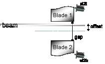
Instead, it would be more useful for the user to control the experiment by means of changing the gap and offset values. Pseudo motors gap and offset will provide the necessary interface for controlling the experiments gap and offset values respectively.
The calculations that need to be performed are:
![\[ \left\{ \begin{array}{l} gap=sl2t+sl2b\\ offset=\frac{sl2t-sl2b}{2}\end{array}\right.\]](../../_images/math/cb4862f68f596f293079277b7ddf5e81dd0f23ad.png)
![\[ \left\{ \begin{array}{l} sl2t=-offset+\frac{gap}{2}\\ sl2b=offset+\frac{gap}{2}\end{array}\right.\]](../../_images/math/a008896ef4107f0cd38f049efc8fef5fab11f0df.png)
The corresponding python code would be:
01  class Slit(PseudoMotor):
02      """A Slit system for controlling gap and offset pseudo motors."""
04
05      pseudo_motor_roles = ("Gap", "Offset")
06      motor_roles = ("Motor on blade 1", "Motor on blade 2")
07
08  def calc_physical(self,index,pseudo_pos,params = None):
09      half_gap = pseudo_pos[0]/2.0
10      if index == 0:
11          return -pseudo_pos[1] + half_gap
12      else
13          return pseudo_pos[1] + half_gap
14
15  def calc_pseudo(self,index,physical_pos,params = None):
16      if index == 0:
17          return physical_pos[1] + physical_pos[0]
18      else:
19          return (physical_pos[1] - physical_pos[0])/2.0
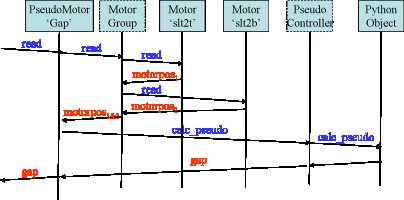
read gap position diagram
The following diagram shows the sequence of operations performed when the position is requested from the gap pseudo motor:
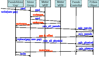
write gap position diagram
The following diagram shows the sequence of operations performed when a new position is written to the gap pseudo motor:
The Counter/Timer interface
The Counter/Timer user interface
The Counter/Timer interface is statically linked with the Pool device server and supports several attributes and commands. It is implemented in C++ and used a set of the so-called “controller” methods. The Counter/Timer interface is always the same whatever the hardware is. This is the rule of the “controller” to access the hardware using the communication link supported by the hardware (network link, Serial line…).
The controller code has a well-defined interface and can be written using Python or C++. In both cases, it will be dynamically loaded into the pool device server process.
The states
The Counter/Timer interface knows four states which are ON, MOVING, FAULT and UNKNOWN. A Counter/Timer device is in MOVING state when it is counting! It is in FAULT if its controller software is not available (impossible to load it), if a fault is reported from the hardware controller or if the controller software returns an unforeseen state. The device is in the UNKNOWN state if an exception occurs during the communication between the pool and the hardware controller.
The commands
The Counter/Timer interface supports 2 commands on top of the Tango classical Init, State and Status commands. These commands are summarized in the following table:
| Command name | Input data type | Output data type |
|---|---|---|
| Start | void | void |
| Stop | void | void |
- Start : When the device is used as a counter, this commands allows the counter to start counting. When it is used as a timer, this command starts the timer. This command changes the device state from ON to MOVING. It is not allowed to execute this command if the device is already in the MOVING state.
- Stop : When the device is used as a counter, this commands stops the counter. When it is used as a timer, this command stops the timer. This commands changes the device state from MOVING to ON. It is a no action command if this command is received and the device is not in the MOVING state.
The attributes
The Counter/Timer interface supports several attributes which are summarized in the following table:
| Name | Data type | Data format | Writable | Memorized | Ope/Expert |
|---|---|---|---|---|---|
| Value | Tango::DevDouble | Scalar | R/W | No | Ope |
| SimulationMode | Tango::DevBoolean | Scalar | R | No | Ope |
- Value : This is read-write scalar double attribute. Writing the value is used to clear (or to preset) a counter or to set a timer time. For counter, reading the value allows the user to get the count number. For timer, the read value is the elapsed time since the timer has been started. After the acquisition, the value stays unchanged until a new count/time is started. For timer, the unit of this attribute is the second.
- SimulationMode : This is a read only scalar boolean attribute. When set, all the counting/timing requests are not forwarded to the software controller and then to the hardware. When set, the device Value is always 0. To set this attribute, the user has to used the pool device Tango interface. It is not allowed to read this attribute when the device is in FAULT or UNKNOWN states.
The properties
Each Counter/Timer device has one property which is automatically managed by the pool software and must not be changed by the user. This property is named Channel_id.
The Counter/Timer controller
The CounterTimer controller follows the same principles already explained for the Motor controller in chapter XXX: Unknown inset LatexCommand ref{sub:The-Motor-Controller}:
The basic
For Counter/Timer, the pre-defined set of methods which has to be implemented can be splitted in 7 different types which are:
- Methods to create/remove counter/timer experiment channel
- Methods to get channel(s) state
- Methods to read channel(s)
- Methods to load channel(s)
- Methods to start channel(s)
- Methods to configure a channel
- Remaining method
The CounterTimer controller features
Not defined yet
The CounterTimer controller extra attributes
The definition is the same than the one defined for Motor controller and explained in chapter XXX: Unknown inset LatexCommand ref{par:Specifying-the-motor}:
Methods to create/remove Counter Timer Channel
Two methods are called when creating or removing counter/timer channel from a controller. These methods are called AddDevice and DeleteDevice . The AddDevice method is called when a new channel belonging to the controller is created within the pool. The DeleteDevice method is called when a channel belonging to the controller is removed from the pool.
Method(s) to get Counter Timer Channel state.
These methods follow the same definition than the one defined for Motor controller which are detailed in chapter XXX: Unknown inset LatexCommand ref{par:Methods-to-get-state}: .
Method(s) to read Counter Timer Experiment Channel
Four methods are used when a request to read channel(s) value is received. These methods are called PreReadAll, PreReadOne, ReadAll and ReadOne. The algorithm used to read value of one or several channels is the following :
/FOR/ Each controller(s) implied in the reading
     - Call PreReadAll()
/END FOR/

/FOR/ Each channel(s) implied in the reading
     - PreReadOne(channel to read)
/END FOR/

/FOR/ Each controller(s) implied in the reading
     - Call ReadAll()
/END FOR/

/FOR/ Each channel(s) implied in the reading
     - Call ReadOne(channel to read)
/END FOR/
The following array summarizes the rule of each of these methods:
| Default action | Does nothing | Does nothing | Does nothing | Print message on the screen and returns NaN. Mandatory for Python |
| Externally called by | Reading the Value attribute | Reading the Value attribute | Reading the Value attribute | Reading the Value attribute |
| Internally called | Once for each implied controller | For each implied channel | For each implied controller | Once for each implied channel |
| Typical rule | Init internal data for reading | Memorize which channel has to be read | Send order to physical controller | Return channel value from internal data |
This algorithm covers the sophisticated case where a physical controller is able to read several channels positions at the same time. For some simpler controller, it is possible to implement only the ReadOne() method. The default implementation of the three remaining methods is defined in a way that the algorithm works even in such a case.
Method(s) to load Counter Timer Experiment Channel
Four methods are used when a request to load channel(s) value is received. These methods are called PreLoadAll, PreLoadOne, LoadAll and LoadOne. The algorithm used to load value in one or several channels is the following:
/FOR/ Each controller(s) implied in the loading
     - Call PreLoadAll()
/END FOR/

/FOR/ Each channel(s) implied in the loading
     - ret = PreLoadOne(channel to load,new channel value)
     - /IF/ ret is true
          - Call LoadOne(channel to load, new channel value)
     - /END IF/
/END FOR/

/FOR/ Each controller(s) implied in the loading
     - Call LoadAll()
/END FOR/
The following array summarizes the rule of each of these methods:
| Default action | Does nothing | Returns true | Does nothing | Does nothing |
| Externally called by | Writing the Value attribute | Writing the Value attribute | Writing the Value attribute | Writing the Value attribute |
| Internally called | Once for each implied controller | For each implied channel | For each implied channel | Once for each implied controller |
| Typical rule | Init internal data for loading | Check if counting is possible | Set new channel value in internal data | Send order to physical controller |
This algorithm covers the sophisticated case where a physical controller is able to write several channels positions at the same time. For some simpler controller, it is possible to implement only the LoadOne() method. The default implementation of the three remaining methods is defined in a way that the algorithm works even in such a case.
Method(s) to start Counter Timer Experiment Channel
Four methods are used when a request to start channel(s) is received. These methods are called PreStartAllCT, PreStartOneCT, StartAllCT and StartOneCT. The algorithm used to start one or several channels is the following:
/FOR/ Each controller(s) implied in the starting
     - Call PreStartAllCT()
/END FOR/

/FOR/ Each channel(s) implied in the starting
     - ret = PreStartOneCT(channel to start)
     - /IF/ ret is true
          - Call StartOneCT(channel to start)
     - /END IF/
/END FOR/

/FOR/ Each controller(s) implied in the starting
     - Call StartAllCT()
/END FOR/
The following array summarizes the rule of each of these methods:
| Default action | Does nothing | Returns true | Does nothing | Does nothing |
| Externally called by | The Start command | The Start command | The Start command | The Start command |
| Internally called | Once for each implied controller | For each implied channel | For each implied channel | Once for each implied controller |
| Typical rule | Init internal data for starting | Check if starting is possible | Set new channel value in internal data | Send order to physical controller |
This algorithm covers the sophisticated case where a physical controller is able to write several channels positions at the same time. For some simpler controller, it is possible to implement only the StartOneCT() method. The default implementation of the three remaining methods is defined in a way that the algorithm works even in such a case.
Methods to configure Counter Timer Experiment Channel
The rule of these methods is to
- Get or Set channel extra attribute(s) parameter with methods called GetExtraAttributePar() or SetExtraAttributePar()
The following table summarizes the usage of these methods:
| Called by | Reading any of the extra attributes | Writing any of the extra attributes |
| Rule | Get extra attribute value from the physical layer | Set additional attribute value in physical controller |
The GetExtraAttributePar() default implementation returns a string set to “Pool_meth_not_implemented”.
Remaining methods
The rule of the remaining methods is to
- Send a raw string to the controller with a method called SendToCtrl()
- Abort a counting counter/timer with a method called AbortOne()
The following table summarizes the usage of this method:
| Called by | The Pool SendToController command | The Stop CounterTimer command |
| Rule | Send the input string to the controller and returns the controller answer | Abort a running count |
The Counter Timer controller properties (including the MaxDevice
property)
The definition is the same than the one defined for Motor controller and explained in chapter XXX: Unknown inset LatexCommand ref{par:Controller-properties}:
C++ controller
For C++, the controller code is implemented as a set of classes: A base class called Controller and a class called CoTiController which inherits from Controller. Finally, the user has to write its controller class which inherits from CoTiController. The Controller class has already been detailed in XXX: Unknown inset LatexCommand ref{sub:The-Cpp-Controller-class}: .
XXX: Unknown layout Subparagraph: The CoTiController class The CoTiController class defines thirteen virtual methods which are:
- void CoTiController::PreReadAll () The default implementation does nothing
- void CoTiController::PreReadOne (long idx_to_read) The default implementation does nothing
- void CoTiController::ReadAll () The default implementation does nothing
- double CoTiController::ReadOne (long idx_to_read) The default implementation prints a message on the screen and return a NaN value
- void CoTiController::PreLoadAll () The default implementation does nothing
- bool CoTiController::PreLoadOne (long idx_to_load,double new_value) The default implementation returns true
- void CoTiController::LoadOne (long idx_to_load,double new_value) The default implementation does nothing
- void CoTiController::LoadAll () The default implementation does nothing
- void CoTiController::PreStartAllCT () The default implementation does nothing
- bool CoTiController::PreStartOneCT (long idx_to_start) The default implementation returns true
- void CoTiController::StartOneCT (long idx_to_start) The default implementation does nothing
- void CoTiController::StartAllCT () The default implementation does nothing
- void CoTiController::AbortOne (long idx_to_abort) The default implementation does nothing
This class has one constructor which is
- CoTiController::CoTiController (const char *) Constructor of the CoTiController class with the controller instance name as parameter
XXX: Unknown layout Subparagraph: The user controller class The user has to implement the remaining pure virtual methods (AddDevice and DeleteDevice) and has to re-define virtual methods if the default implementation does not cover his needs. The controller code has to define two global variables which are:
- CounterTimer_Ctrl_class_name : This is an array of classical C strings terminated by a NULL pointer. Each array element is the name of a Counter Timer Channel controller defined in the file.
- <CtrlClassName>_MaxDevice : Idem motor controller definition
On top of that, a controller code has to define a C function to create the controller object. This is similar to the Motor controller definition which is documented in XXX: Unknown inset LatexCommand ref{par:The-user-controller}:
Python controller
The principle is exactly the same than the one used for C++ controller but we don’t have pure virtual methods with a compiler checking if they are defined at compile time. Therefore, it is the pool software which checks that the following methods are defined within the controller class when the controller module is loaded (imported):
- AddDevice
- DeleteDevice
- ReadOne method
- StateOne method
- StartOneCT or StartAllCT method
- LoadOne or LoadAll method
With Python controller, there is no need for function to create controller class instance. With the help of the Python C API, the pool device is able to create the needed instances. Note that the StateOne() method does not have the same signature for Python controller.
tuple Stat e One (self,idx_number) Get a channel state. The method has to return a tuple with one or two elements which are:
- The channel state (as defined by Tango)
- A string describing the motor fault if the controller has this feature.
A Python controller class has to inherit from a class called CounterTimerController . This does not add any feature but allows the pool software to realize that this class is a Counter Timer Channel controller.
The Unix Timer
A timer using the Unix getitimer() and setitimer() system calls is provided. It is a Counter/Timer C++ controller following the definition of the previous chapter. Therefore, the device created using this controller will have the Tango interface as the one previously described.
The Unix Timer controller shared library is called UxTimer.so and the Controlller class is called UnixTimer . This controller is foresee to have only one device (MaxDevice = 1)
The ZeroDExpChannel interface
The ZeroDExpChannel is used to access any kind of device which returns a scalar value and which are not counter or timer. Very often (but not always), this is a commercial measurement equipment connected to a GPIB bus. In order to have a precise as possible measurement, an acquisition loop is implemented for these ZeroDExpChannel device. This acquisition loop will simply read the data from the hardware as fast as it can (only “sleeping” 20 mS between each reading) and a computation is done on the resulting data set to return only one value. Three types of computation are foreseen. The user selects which one he needs with an attribute. The time during which this acquisition loop will get data is also defined by an attribute
The ZeroDExpChannel user interface
The ZeroDExpChannel interface is statically linked with the Pool device server and supports several attributes and commands. It is implemented in C++ and used a set of the so-called “controller” methods. The ZeroDExpChannel interface is always the same whatever the hardware is. This is the rule of the “controller” to access the hardware using the communication link supported by the hardware (network link, GPIB…).
The controller code has a well-defined interface and can be written using Python or C++. In both cases, it will be dynamically loaded into the pool device server process.
The states
The ZeroDExpChannel interface knows five states which are ON, MOVING, ALARM, FAULT and UNKNOWN. A ZeroDExpChannel device is in MOVING state when it is acquiring data! It is in ALARM state when at least one error has occured during the last acquisition. It is in FAULT if its controller software is not available (impossible to load it), if a fault is reported from the hardware controller or if the controller software returns an unforeseen state. The device is in the UNKNOWN state if an exception occurs during the communication between the pool and the hardware controller.
The commands
The ZeroDExpChannel interface supports 2 commands on top of the Tango classical Init, State and Status commands. These commands are summarized in the following table:
| Command name | Input data type | Output data type |
|---|---|---|
| Start | void | void |
| Stop | void | void |
- Start : Start the acquisition for the time defined by the attribute CumulatedTime. If the CumulatedTime attribute value is 0, the acquisition will not automatically stop until a Stop command is received. This command changes the device state from ON to MOVING. It is not allowed to execute this command if the device is already in the MOVING state.
- Stop : Stop the acquisition. This commands changes the device state from MOVING to ON. It is a no action command if this command is received and the device is not in the MOVING state.
The attributes
The ZeroDExpChannel interface supports several attributes which are summarized in the following table:
| Name | Data type | Data format | Writable | Memorized | Ope/Expert |
|---|---|---|---|---|---|
| Value | Tango::DevDouble | Scalar | R | No | Ope |
| CumulatedValue | Tango::DevDouble | Scalar | R | No | Ope |
| CumulationTime | Tango::DevDouble | Scalar | R/W | Yes | Ope |
| CumulationType | Tango::DevLong | Scalar | R/W | Yes | Ope |
| CumulatedPointsNumber | Tango::DevLong | Scalar | R | No | Ope |
| CumulatedPointsError | Tango::DevLong | Scalar | R | No | Ope |
| SimulationMode | Tango::DevBoolean | Scalar | R | No | Ope |
Value : This is read scalar double attribute. This is the live value reads from the hardware through the controller
CumulatedValue : This is a read scalar double attribute. This is the result of the data acquisition after the computation defined by the CumulationType attribute has been applied. This value is 0 until an acquisition has been started. After an acquisition, the attribute value stays unchanged until the next acquisition is started. If during the acquisition some error(s) has been received while reading the data, the attribute quality factor will be set to ALARM
CumulationTime : This is a read-write scalar double and memorized attribute. This is the acquisition time in seconds. The acquisition will automatically stops after this CumulationTime. Very often, reading the hardware device to get one data is time-consuming and it is not possible to read the hardware a integer number of times within this CumulationTime. A device property called StopIfNoTime (see XXX: Unknown inset LatexCommand ref{ite:StopIfNoTime:-A-boolean}: ) allows the user to tune the acquisition loop.
CumulationType : This a read-write scalar long and memorized attribute. Defines the computation type done of the values gathered during the acquisition. Three type of computation are supported:
- Sum: The CumulatedValue attribute is the sum of all the data read during the acquisition. This is the default type.
- Average: The CumulatedValue attribute is the average of all the data read during the acquisition
- Integral: The CumulatedValue attribute is a type of the integral of all the data read during the acquisition
CumulatedPointsNumber : This is a read scalar long attribute. This is the number of data correctly read during the acquisition. The attribute value is 0 until an acquisition has been started and stay unchanged between the end of the acquisition and the start of the next one.
CumulatedPointsError : This is a read scalar long attribute. This is the number of times it was not possible to read the data from the hardware due to error(s). The property ContinueOnError allows the user to define what to do in case of error. The attribute value is 0 until an acquisition has been started and stay unchanged between the end of the acquisition and the start of the next one.
SimulationMode : This is a read only scalar boolean attribute. When set, all the acquisition requests are not forwarded to the software controller and then to the hardware. When set, the device Value, CumulatedValue, CumulatedPointsNumber and CumulatedPointsError are always 0. To set this attribute, the user has to used the pool device Tango interface. The value of the CumulationTime and CumulationType attributes are memorized at the moment this attribute is set. When this mode is turned off, if the value of any of the previously memorized attributes has changed, it is reapplied to the memorized value. It is not allowed to read this attribute when the device is in FAULT or UNKNOWN states.
The properties
Each ZeroDExpChannel device has a set of properties. One of these properties is automatically managed by the pool software and must not be changed by the user. This property is named Channel_id. The user properties are:
| Property name | Default value |
|---|---|
| StopIfNoTime | true |
| ContinueOnError | true |
- XXX: Unknown inset LatexCommand label{ite:StopIfNoTime:-A-boolean}: StopIfNoTime : A boolean property. If this property is set to true, the acquisition loop will check before acquiring a new data that it has enough time to do this. To achieve this, the acquisition loop measures the time needed by the previous data read and checks that the actual time plus the acquisition time is still less than the CumulationTime. If not, the acquisition stops. When this property is set to false, the acquisition stops when the acquisition time is greater or equal than the CumulationTime
- ContinueOnError : A boolean property. If this property is set to true (the default), the acquisition loop continues reading the data even after an error has been received when trying to read data. If it is false, the acquisition stops as soon as an error is detected when trying to read data from the hardware.
Getting ZeroDExpChannel state using event
The simplest way to know if a Zero D Experiment Channel is acquiring data is to survey its state. If the device is acquiring data, its state will be MOVING. When the acquisition is over, its state will be back to ON. The pool ZeroDExpChannel interface allows client interested by Experiment Channel state value to use the Tango event system subscribing to channel state change event. As soon as a channel starts an acquisition, its state is changed to MOVING and an event is sent. As soon as the acquisition is over (for one reason or another), the channel state is updated and another event is sent.
XXX: Unknown inset LatexCommand label{par:Reading-the-ZeroDExpChannel}:
Reading the ZeroDExpChannel CumulatedValue attribute
During an acquisition, events with CumulatedValue attribute are sent from the device server to the interested clients. The acquisition loop will periodically read this event and fire an event. The first and the last events fired during the acquisition loop do not check the change event criteria. The other during the acquisition loop check the change event criteria
The ZeroDExpChannel Controller
The ZeroDExpChannel controller follows the same principles already explained for the Motor controller in chapter XXX: Unknown inset LatexCommand ref{sub:The-Motor-Controller}:
The basic
For Zero Dimension Experiment Channel, the pre-defined set of methods which has to be implemented can be splitted in 5 different types which are:
- Methods to create/remove zero dimension experiment channel
- Methods to get channel(s) state
- Methods to read channel(s)
- Methods to configure a channel
- Remaining method
The ZeroDExpChannel controller features
Not defined yet
The ZeroDExpChannel controller extra attributes
The definition is the same than the one defined for Motor controller and explained in chapter XXX: Unknown inset LatexCommand ref{par:Specifying-the-motor}:
Methods to create/remove Zero D Experiment Channel
Two methods are called when creating or removing experiment channel from a controller. These methods are called AddDevice and DeleteDevice . The AddDevice method is called when a new channel belonging to the controller is created within the pool. The DeleteDevice method is called when a channel belonging to the controller is removed from the pool.
Method(s) to get Zero D Experiment Channel state.
These methods follow the same definition than the one defined for Motor controller which are detailed in chapter XXX: Unknown inset LatexCommand ref{par:Methods-to-get-state}: .
Method(s) to read Zero D Experiment Channel
Four methods are used when a request to read channel(s) value is received. These methods are called PreReadAll, PreReadOne, ReadAll and ReadOne. The algorithm used to read value of one or several channels is the following:
/FOR/ Each controller(s) implied in the reading
     - Call PreReadAll()
/END FOR/

/FOR/ Each channel(s) implied in the reading
     - PreReadOne(channel to read)
/END FOR/

/FOR/ Each controller(s) implied in the reading
     - Call ReadAll()
/END FOR/

/FOR/ Each channel(s) implied in the reading
     - Call ReadOne(channel to read)
/END FOR/
The following array summarizes the rule of each of these methods:
| Default action | Does nothing | Does nothing | Does nothing | Print message on the screen and returns NaN. Mandatory for Python |
| Externally called by | Reading the Value attribute | Reading the Value attribute | Reading the Value attribute | Reading the Value attribute |
| Internally called | Once for each implied controller | For each implied channel | For each implied controller | Once for each implied channel |
| Typical rule | Init internal data for reading | Memorize which channel has to be read | Send order to physical controller | Return channel value from internal data |
This algorithm covers the sophisticated case where a physical controller is able to read several channels positions at the same time. For some simpler controller, it is possible to implement only the ReadOne() method. The default implementation of the three remaining methods is defined in a way that the algorithm works even in such a case.
Methods to configure Zero D Experiment Channel
The rule of these methods is to
- Get or Set channel extra attribute(s) parameter with methods called GetExtraAttributePar() or SetExtraAttributePar()
The following table summarizes the usage of these methods:
| Called by | Reading any of the extra attributes | Writing any of the extra attributes |
| Rule | Get extra attribute value from the physical layer | Set additional attribute value in physical controller |
The GetExtraAttributePar() default implementation returns a string set to “Pool_meth_not_implemented”.
Remaining method
The rule of the remaining method is to
- Send a raw string to the controller with a method called SendToCtrl()
The following table summarizes the usage of this method:
| Called by | The Pool SendToController command |
| Rule | Send the input string to the controller and returns the controller answer |
The ZeroDExpChannel controller properties (including the MaxDevice property)
The definition is the same than the one defined for Motor controller and explained in chapter XXX: Unknown inset LatexCommand ref{par:Controller-properties}:
C++ controller
For C++, the controller code is implemented as a set of classes: A base class called Controller and a class called ZeroDController which inherits from Controller. Finally, the user has to write its controller class which inherits from ZeroDController. The Controller class has already been detailed in XXX: Unknown inset LatexCommand ref{sub:The-Cpp-Controller-class}: .
XXX: Unknown layout Subparagraph: The ZeroDController class The ZeroDController class defines four virtual methods which are:
- void ZeroDController::PreReadAll () The default implementation does nothing
- void ZeroDController::PreReadOne (long idx_to_read) The default implementation does nothing
- void ZeroDController::ReadAll () The default implementation does nothing
- double ZeroDController::ReadOne (long idx_to_read) The default implementation prints a message on the screen and return a NaN value
This class has one constructor which is
- ZeroDController::ZeroDController (const char *) Constructor of the ZeroDController class with the controller instance name as parameter
XXX: Unknown layout Subparagraph: The user controller class The user has to implement the remaining pure virtual methods (AddDevice and DeleteDevice) and has to re-define virtual methods if the default implementation does not cover his needs. The controller code has to define two global variables which are:
- ZeroDExpChannel_Ctrl_class_name : This is an array of classical C strings terminated by a NULL pointer. Each array element is the name of a ZeroDExpChannel controller defined in the file.
- <CtrlClassName>_MaxDevice : Idem motor controller definition
On top of that, a controller code has to define a C function to create the controller object. This is similar to the Motor controller definition which is documented in XXX: Unknown inset LatexCommand ref{par:The-user-controller}:
Python controller
The principle is exactly the same than the one used for C++ controller but we don’t have pure virtual methods with a compiler checking if they are defined at compile time. Therefore, it is the pool software which checks that the following methods are defined within the controller class when the controller module is loaded (imported):
- AddDevice
- DeleteDevice
- ReadOne method
- StateOne method
With Python controller, there is no need for function to create controller class instance. With the help of the Python C API, the pool device is able to create the needed instances. Note that the StateOne() method does not have the same signature for Python controller.
tuple Stat e One (self,idx_number) Get a channel state. The method has to return a tuple with one or two elements which are:
- The channel state (as defined by Tango)
- A string describing the motor fault if the controller has this feature.
A Python controller class has to inherit from a class called ZeroDController . This does not add any feature but allows the pool software to realize that this class is a Zero D Experiment Channel controller.
The OneDExpChannel interface
To be filled in
The TwoDExpChannel interface
To be filled in
The Measurement Group interface
The measurement group interface allows the user to access several data acquisition channels at the same time. It is implemented as a C++ Tango device that is statically linked with the Pool device server. It supports several attributes and commands.
The measurement group is the key interface to be used when getting data. The Pool can have several measurement groups but only one will be ‘in use’ at a time. When creating a measurement group, the user can define four kinds of channels which are:
- Counter/Timer
- ZeroDExpChannel
- OneDExpChannel
- TwoDExpChannel
In order to properly use the measurement group, one of the channels has to be defined as the timer or the monitor. It is not possible to have several times the same channel in a measurement group. It is also not possible to create two measurement groups with exactly the same channels.
The States
The measurement group interface knows five states which are ON, MOVING, ALARM, FAULT. A group is in MOVING state when it is acquiring data (which means that the timer/monitor channel is in MOVING state). A STANDBY state means that the group is not the current active group of the Pool it belongs to. An ON state means that the group is ready to be used. ALARM means that no timer or monitor are defined for the group. If at least one of the channels reported a FAULT by the controller(s) of that(those) channel(s), the group will be in FAULT state.
The commands
The measurement group interface supports three commands on top of the Tango Init, State and Status commands. These commands are summarized in the following table:
| Command name | Input data type | Output data type |
|---|---|---|
| Start | void | void |
| Abort | void | void |
| AddExpChannel | String | void |
| RemoveExpChannel | String | void |
- Start : When the device is in timer mode (Integration_time attribute > 0), it will start counting on all channels at the same time until the timer channel reaches a value of the Integration_time attribute. When the device in in monitor mode (Integration_count attribute > 0), it will start counting on all channels at the same time until de monitor channel reaches the value of the Integration_count attribute. For more details on setting the acquisition mode see XXX: Unknown inset LatexCommand ref{Measurement Group: The attributes}: . This command will change the device state to MOVING. It will not be allowed to execute this command if the device is already in MOVING state. This command does not have any input or output arguments. The state will change from MOVING to ON only when the last channel reports that its acquisition has finished.
- Abort : It aborts the running data acquisition. It will stop each channel member of the measurement group. This command does not have any input or output arguments.
- AddExpChannel : adds a new experiment channel to the measurement group. The given string argument must be a valid experiment channel in the pool and must not be one of the channels of the measurement group. An event will be sent on the corresponding attribute representing the list of channels in the measurement group. For example, if the given channel is a Counter/Timer channel, then an event will be sent for the attribute “Counters “(See below for a list of attributes in the measurement group).
- RemoveExpChannel : removes the given channel from the measurement group. The given string argument must be a valid experiment channel in the measurement group. If the channel to be deleted is the current Timer/Monitor then the value for the corresponding attribute will be set to “Not Initialized “and an event will be sent. An event will be sent on the corresponding attribute representing the list of channels in the measurement group.
XXX: Unknown inset LatexCommand label{Measurement Group: The attributes}:
The attributes
A measurement group will support 8+n (n being the number of channels)
attributes summarized in the following table:
========================================= ================ ===================== ======== ========= ==========
Name Data type Data format Writable Memorized Ope/Expert
========================================= ================ ===================== ======== ========= ==========
Integration_time Tango::DevDouble Scalar R/W Yes Ope
Integration_count Tango::DevLong Scalar R/W Yes Ope
Timer Tango::DevString Scalar R/W Yes Ope
Monitor Tango::DevString Scalar R/W Yes Ope
Counters Tango::DevString Spectrum R No Ope
ZeroDExpChannels Tango::DevString Spectrum R No Ope
OneDExpChannels Tango::DevString Spectrum R No Ope
TwoDExpChannels Tango::DevString Spectrum R No Ope
<channel_name  >_Value Tango::DevDouble Scalar/Spectrum/Image R No Ope
========================================= ================ ===================== ======== ========= ==========
>_Value Tango::DevDouble Scalar/Spectrum/Image R No Ope
========================================= ================ ===================== ======== ========= ==========
- Integration_time : The group timer integration time. Setting this value to >0 will set the measurement group acquisition mode to timer. It will force Integration_count attribute to 0 (zero). It will also exclude the current Timer channel from the list of Counters. Units are in seconds.
- Integration_count : The group monitor count value. Setting this value to >0 will set the measurement group acquisition mode change to monitor. It will force Integration_time attribute to 0 (zero).
- Timer : The name of the channel used as a Timer. A “Not Initialized “value means no timer is defined
- Monitor : The name of the channel used as a Monitor. A “Not Initialized “value means no timer is defined
- Counter : The list of counter names in the group
- ZeroDExpChannels : The list of 0D Experiment channel names in the group
- OneDExpChannels : The list of 1D Experiment channel names in the group
- TwoDExpChannels : The list of 2D Experiment channel names in the group
- <channel_name >_Value : (with
 ) attributes dynamically created (one for each channel) which will
contain the corresponding channel Value(for Counter/Timer, 1D or
2DExpChannels), CumulatedValue(for 0DExpChannels). For Counter/Timers
and 0DExpChannels the data format will be Scalar. For 1DExpChannels it
will be Spectrum and for 2DExpChannels it will be Image.
) attributes dynamically created (one for each channel) which will
contain the corresponding channel Value(for Counter/Timer, 1D or
2DExpChannels), CumulatedValue(for 0DExpChannels). For Counter/Timers
and 0DExpChannels the data format will be Scalar. For 1DExpChannels it
will be Spectrum and for 2DExpChannels it will be Image.
The properties
Device properties
Each measurement group has five properties. All of them are managed automatically by the pool software and must not be changed by the user. These properties are called Measurement_group_id, Pool_device, CT_List, ZeroDExpChannel_List, OneDExpChannel_List, TwoDExpChannel_List.
XXX: Unknown inset LatexCommand label{measurement group:Checking-operation-modes}:
Checking operation mode
Currently, the measurement group supports two operation modes. The table below shows how to determine the current mode for a measurement group.
| mode | Integration_time | Integration_count |
|---|---|---|
| Timer | >0.0 | 0 |
| Monitor | 0.0 | >0 |
| Undef | 0.0 | 0 |
‘Undef’ means no valid values are defined in Integration_time and in Integration_count. You will not be able to execute the Start command in this mode.
Getting measurement group state using event
The simplest way to know if a measurement group is acquiring data is to survey its state. If a measurement group is acquiring data its state will be MOVING. When the data acquisition is over, its state will change back to ON. The data acquisition is over when the measurement group detects that all channels finished acquisition (their state changed from MOVING to ON).The pool group interface allows clients interested in group state to use the Tango event system subscribing to measurement group state change event. As soon as a group starts acquiring data, its state is changed to MOVING and an event is sent. A new event will be sent when the data acquisition ends. Events will also be sent to each channel of the group when they start acquiring data and when they stop.
Reading the measurement group channel values
For each measurement group there is a set of key dynamic attributes
representing the value of each channel in the group. They are named
<channel_name >_Value. Special care has been taken on the management of these
attributes with distinct behavior depending on the type of channel the
attribute represents (Counter/Timer, 0D, 1D or 2D channel).
Counter/Timer channel values
A Counter/Timer Value is represented by a scalar read-only double attribute. When the measurement group is not taking data, reading the counter/timer value will generate calls to the controller and therefore hardware access. When the group is taking data (master channel is moving), the value of a counter/timer is read every 100 miliseconds and stored in the Tango polling buffer. This means that a client reading the value of the channel while the group is moving will get the value from the Tango polling buffer and will not generate exra controller calls. It is also possible to get the value using the Tango event system. When the group is moving, an event is sent to the registered clients when the change event criteria is true. This is applicable for each Counter/Timer channel in the group. By default, this change event criterion is set to be an absolute difference in the value of 5.0. It is tunable by attribute using the classical “abs_change “property or the pool device basis using its defaultCtGrpVal_AbsChange property. Anyway, not more than 10 events could be sent by second. Once the data acquisition is over, the value is made unavailable from the Tango polling buffer and is read a last time. A forced change event is sent to clients using events.
Zero D channel values
A ZeroDExpChannel CumulatedValue is represented by a scalar read-only double attribute. Usually a ZeroDChannel represents the value of a single device (ex.: multimeter). Therefore, has hardware access cannot be optimized for a group of devices, reading the value on the measurement group device attribute has exactly the same behavior as reading it directly on the CumulatedValue attribute of the ZeroDChannel device (see XXX: Unknown inset LatexCommand ref{par:Reading-the-ZeroDExpChannel}: ).
One D channel values
To be filled in
Two D channel values
To be filled in
Performance
Measurement group devices can often contain many channels. Client
applications often request channel values for the set (or subset) of
channels in a group. Read requests for these channel values through
the <channel_name >_Value attributes of a measurement group should be done by clients in
groups as often as possible. This can be achieved by using the client
Tango API call read_attributes on a DeviceProxy object. This will
ensure maximum performance by minimizing hardware access since the
measurement group can order channel value requests per controller thus
avoiding unecessary calls to the hardware.
Measurement group configuration
Timer/Monitor
Measurement group operation mode can be checked/set through the Integration_time and Integration_count (see XXX: Unknown inset LatexCommand ref{measurement group:Checking-operation-modes}: ). Setting the Integration_time to >0.0 will make the data acquisition (initiated by the invoking the Start command) finish when the channel defined in the Timer attribute reaches the value of Integration_time. Setting the Integration_count to >0 will make the data acquisition (initiated by the invoking the Start command) finish when the channel defined in the Monitor attribute reaches the value of Integration_count.
In either case, the measurement group will NOT assume that the master channel(timer/monitor) is able to stop all the other channels in the group, so it will force a Stop on these channels as soon as it detects that the master has finished. This is the case of the UnixTimer channel which itself has no knowledge of the channels involved and therefore is not able to stop them directly.
Integration_time, Integration_count, timer and monitor are memorized attributes. This means that the configuration values of these attributes are stored in the database. The next time the Pool starts the values are restored. This is done in order to reduce Pool configuration at startup to the minimum.
The ghost measurement group
In order to allow pool client software to be entirely event based, some kind of polling has to be done on each channel to inform them on state change which are not related to data acquisition. To achieve this goal, one internally managed measurement group is created. Each pool channel (counter/timer, 0D, 1D or 2D experiment channel) is a member of this group. The Tango polling thread polls the state command of this group (Polling period tunable with the pool Ghostgroup_PollingPeriod property). The code of this group state command detects change in every channel state and send a state change event on the corresponding channel. This measurment group is not available to client and is even not defined in the Tango database. This is why it is called the ghost measurement group.
The pool serial line, GPIB, socket interfaces
To be filled in
The pool Modbus interface
To be filled in
Extending pool features
To be filled in
Common task handled by the pool
Constraint
Two types of constraint are identified.
Simple constraint: This type of constraint is valid only for motor motion. It limits motor motion. This in not the limit switches which are a hardware protection. It’s a software limit. This type of constraint is managed by the min_value and max_value property of the motor Position Tango attribute. Tango core will refused to write the attribute (Position) if outside the limits set by these min_value and max_value attribute properties. These values are set on motor Position attribute in physical unit. Warning : The backlash has to be taken into account in the management of this limit. In order to finish the motion always coming from the same direction, sometimes the motor has to go a little bit after the wanted position and then returns to the desired position. The limit value has to take the backlash value into account. If the motor backlash attribute is modified, it will also change the Position limit value.
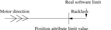
User constraint: This kind of constraint is given to the user to allow him to write constraint macros which will be executed to allow or disallow an action to be done on one object. In the pool case, the object is a writable attribute and the action is writing the attribute. Therefore, the following algorithm is used when writing an attribute with constraint:
/IF/ Simple constraint set
   /IF/ New value outside limits
       - Throw an exception
   /ENDIF/
/ENDIF/

/IF/ Some user constraint associated to this attribute
   /FOR/ All the user constraint
      - Evaluate the constraint
      /IF/ The constraint evaluates to False
          - Throw an exception
      /ENDIF/
   /ENDFOR/
/ENDIF/

- Write the attribute
The first part of this algorithm is part of the Tango core. The second part will be coded in the Pool Tango classes and in a first phase will be available only for the Position attribute of the Motor class.
User constraint implementation
When the user creates a constraint, he has to provide to the pool the following information:
- The name of the object to which the constraint belongs. It is the name of the writable Tango attribute (actually only a motor position attribute.
A user constraint will be written using the Python language. It has to be a Python class with a constructor and a “Evaluate” method. This class has to inherit from a class called PoolConstraint. This will allow the pool software to dynamically discover that this class is a pool constraint. The class may define the depending attributes/devices. A depending attribute/device is an object used to evaluate if the constraint is true or false. The depending attributes have to be defined in a list called depending_attr_list . Each element in this list is a dictionnary with up to 2 elements which are the description of the depending attribute and eventually a default value. The depending devices have to be defined in a list called depending_dev_list which follow the same syntax than the depending_attr_list. A constraint may also have properties as defined in XXX: Unknown inset LatexCommand ref{par:Controller-properties}: . The constructor will receive three input arguments which are:
- A list with the depending attribute name
- A list with the depending device name
- A dictionnary (name:value) with the properties definition
One rule of the constructor is to build the connection with these Tango objects and to keep them in the instance. The Evaluate method will evaluate the constraint and will return true or false. It receives as input argument a list with the result of a read_attribute call executed on all the depending attributes.
Five pool device commands and two attribute allow the management of these constraints. The commands are CreateConstraint , DeleteConstraint , EvaluateContraint, GetConstraintClassInfo and GetConstraint . The attributes are called ConstraintList and ConstraintClassList . They are all detailed in chapters XXX: Unknown inset LatexCommand ref{sub:Device-pool-commands}: and XXX: Unknown inset LatexCommand ref{sub:Device-pool-attributes}: . The following is an example of a user constraint
1 import PyTango
2
3 class MyConstraint(PoolConstraint):
4
5    depending_attr_list = [{'DefaultValue':"first_mot/position",
6                            'Description':"X position"},
7                           {'DefaultValue':"second_mot/position",
8                            'Description':"Z position"},
9                           {'DefaultValue':"first_mot/velocity",
10                           'Description':"X position speed"}]
11
11   depending_dev_list = [{'DefaultValue':"first_dev",
12                          'Description':"Air pressure device"}]
13
14   inst_prop = {'MyProp':{'Type':PyTango.DevLong,'Description':'The psi constant',
15                          'DefaultValue',1234}}
16
17    def __init__(self,attr_list,dev_list,prop_dict)
18       self.air_device = PyTango.DeviceProxy(dev_list[0])
19       self.const = prop_dict["MyProp"]
20
21   def Evaluate(self,att_value):
22      if att_value[0].value > (xxx * self.const)
23         return False
24      elif att_value[1].value > yyy
25         return False
26      elif att_value[2].value > zzz
27         return False
28      elif self.air_device.state() == PyTango.FAULT
29         return False
30      return True
Line 3 : The class inherits from the PoolConstraint class Line 5-10: Definition of the depending attributes Line 11-12: Definition of the depending devices Line 14-15: Definition of a constraint property Line 17-19: The constructor Line 21-30: The Evaluate method
Archiving motor position
XXX: Unknown inset LatexCommand label{sub:Archiving-motor-position}:
It is not possible to archive motor position using the Tango memorized attribute feature because Tango writes the attribute value into the database just after it has been set by the user. In case of motors which need some time to go to the desired value and which from time to time do not go exactly to the desired value (for always possible to have position which is a integer number of motor steps), it is more suited to store the motor position at the end of the motion. To achieve this, the pool has a command (called ArchieveMotorPosition ) which will store new motor positions into the database. This command will be polled by the classical Tango polling thread in order to execute it regularly. The algorithm used by this command is the following:
- Read motors position for all motors which are not actually moving

- /FOR/ all motors
    - /IF/ The new position just read is different than the old one
       - Mark the motor as storable
    - /ENDIF/
- /ENDFOR/

- Store in DB position of all storable motors
- Memorize motors position
In order to minimize the number of calls done on the Tango database, we need to add to the Tango database software the ability to store x properties of one attribute of y devices into the database in one call (or may be simply the same property of one attribute of several device).
Scanning
To be filled in
Experiment management
To be filled in
The pool device Tango interface
The pool is implemented as a C++ Tango device server and therefore supports a set of commands/attributes. It has several attributes to get object (motor, pseudo-motor, controller) list. These lists are managed as attributes in order to have events on them when a new object (motor, controller…) is created/deleted.
Device pool commands
XXX: Unknown inset LatexCommand label{sub:Device-pool-commands}:
On top of the three classical Tango commands (State, Status and Init), the pool device supports the commands summarized in the following table:
| Device type | Name | Input data type | Output data type |
|---|---|---|---|
| related | InitController | Tango::DevString | void |
| commands | ReloadControllerCode SendToController | Tango::DevString Tango::DevVarStringArray | void Tango::DevString |
| Motor | CreateMotor | Tango::DevVarLongStringArray | void |
| related commands | DeleteMotor | Tango::DevString | void |
| Motor group | CreateMotorGroup | Tango::DevVarStringArray | void |
| related commands | DeleteMotorGroup GetPseudoMotorInfo | Tango::DevString Tango::DevVarStringArray | void Tango::DevVarStringArray |
| Pseudo motor | CreatePseudoMotor | Tango::DevVarStringArray | void |
| related commands | DeletePseudoMotor ReloadPseudoMotorCode GetConstraintClassInfo CreateConstraint | Tango::DevString Tango::DevString Tango::DevString Tango::DevVarStringArray | void void Tango::DevVarStringArray void |
| User Constraint | DeleteConstraint | Tango::DevString | void |
| related | EvaluateConstraint | Tango::DevString | Tango::DevBoolean |
| commands | GetConstraint ReloadConstraintCode | Tango::DevString Tango::DevString | Tango::DevVarLongArray void |
| Experiment Channel | CreateExpChannel | Tango::DevVarStringArray | void |
| related commands | DeleteExpChannel | Tango::DevString | void |
| Measurement group | CreateMeasurementGroup | Tango::DevVarStringArray | void |
| related commands | DeleteMeasurementGroup | Tango::DevString | void |
| Dyn loaded Tango | LoadTangoClass | ||
| class related | UnloadTangoClass | ||
| commands | ReloadTangoClass | ||
| Dyn. created | CreateXXX | ||
| commands | DeleteXXX | ||
| Miscellaneous | ArchiveMotorPosition | void | void |
CreateController : This command creates a controller object. It has four arguments (all strings) which are:
The controller device type: Actually three types are supported as device type. They are:
- “Motor” (case independent) for motor device
- “CounterTimer” (case independent) for counter timer device
- “ZeroDExpChannel” (case independent) for zero dimension experiment channel device
Controller code file name: For C++ controller, this is the name of the controller shared library file. For Python controller, this is the name of the controller module. This parameter is only a file name, not a path. The path is automatically taken from the pool device PooPath property. It is not necessary to change your LD_LIBRARY_PATH or PYTHONPATH environment variable. Everything is taken from the PoolPath property.
Controller class name: This is the name of the class implementing the controller. This class has to be implemented within the controller shared library or Python module passed as previous argument
Instance name: It is a string which allows the device pool to deal with several instance of the same controller class. The pool checks that this name is uniq within a control system.
The list of created controllers is kept in one of the pool device property and at next startup time, all controllers will be automatically re-created. If you have several pool device within a control system (the same TANGO_HOST), it is not possible to have two times the same controller defines on different pool device. Even if the full controller name is <Controller file name>.<Controller class name>/<Instance name>, each created controller has an associated name which is:
<Instance name>
which has to be used when the controller name is requested. This name is case independent.
DeleteController : This command has only one input argument which is the controller name (as defined previously). It is not possible to delete a controller with attached device(s). You first have to delete controller’s device(s).
InitController : This command is used to (re)-initialize a controller if the controller initialization done at pool startup time has failed. At startup time, the device pool creates controller devices even if the controller initialization has failed. All controller devices are set to the FAULT state. This command will try to re-create the controller object and if successful, send an “Init” command to every controller devices. Its input argument is the controller name.
GetControllerInfo : This command has three or four input parameters which are: XXX: Unknown inset LatexCommand label{ite:GetControllerInfo:}:
- The controller device type
- The controller code file name: For C++ controller, this is the name of the controller shared library file. For Python controller, this is the name of the controller module. This parameter is only a file name, not a path. The path is automatically taken from the pool device PooPath property.
- The controller class name: This is the name of the class implementing the controller. This class has to be implemented within the controller shared library or Python module passed as previous argument
- The controller instance name: This parameter is optional. If you do not specify it, the command will return information concerning controller properties as defined at the class level. If you defined it, the command will return information concerning controller properties for this specific controller instance.
It returns to the caller all the informations related to controller properties as defined in the controller code and/or in the Tango database. The following format is used to return these informations:
The string describing the controller (or an empty string if not defined)
Number of controller properties
For each property:
- The property name
- The property data type
- The property description
- The property default value (Empty string if not defined)
ReloadControllerCode : The controller code is contains in a shared library dynamically loaded or in a Python module. The aim of this command is to unlink the pool to the shared library and to reload it (or Reload the Python module). The command argument is a string which is the controller file name as defined for the CreateController command. For motor controller, it is not possible to do this command if one of the motor attached to controller(s) using the code within the file is actually moving. All motor(s) attached to every controller(s) using this file is switched to FAULT state during this command execution. Once the code is reloaded, an “Init” command is sent to every controller devices.
SendToController : Send data to a controller. The first element of the input argument array is the controller name. The second one is the string to be sent to the controller. This command returns the controller answer or an empty string is the controller does not have answer.
CreateMotor : This command creates a new motor. It has three arguments which are:
- The motor name (a string). This is a Tango device alias. It is not allowed to have ‘/’ character within this name. It is a case independent name.
- The motor controller name (a string)
- The axe number within the controller
The motor is created as a Tango device and automatically registered in the database. At next startup time, all motors will be automatically re-created. A Tango name is assigned to every motor. This name is a Tango device name (3 fields) and follow the syntax:
motor/controller_instance_name/axe_number
in lower case letters.
DeleteMotor : This command has only one argument which is the motor name as given in the first argument of the CreateMotor command. The device is automatically unregistered from the Tango database and is not accessible any more even for client already connected to it.
CreateMotorGroup : This command creates a new motor group. It has N arguments which are:
- The motor group name (a string). This is a Tango device alias. It is not allowed to have ‘/’ character within this name. It is a case independent name.
- The list of motor element of the group (motor name or another group name or pseudo-motor name)
The motor group is created as a Tango device and automatically registered in the database. At next startup time, all motor groups will be automatically re-created. A Tango name is assigned to every motor group. This name is a Tango device name (3 fields) and follow the syntax:
mg/ds_instance_name/motor_group_name
in lower case letters.
DeleteMotorGroup : This command has only one argument which is the motor group name as given in the first argument of the CreateMotorGroup command. The device is automatically unregistered from the Tango database and is not accessible any more even for client already connected to it. This command is not allowed if another motor group is using the motor group to be deleted.
GetPseudoMotorInfo : XXX: Unknown inset LatexCommand label{sub:GetPseudoMotorClassInfo}: : This command has one input argument (a string):
<module_name>.<class_name>
The command returns a list of strings representing the pseudo motor system information with the following meaning:
pseudo_info[0] - textual description of the pseudo motor class.
pseudo_info[1] - (=M) the number of motors required by this pseudo motor class.
pseudo_info[2] - (=N) the number of pseudo motors that the pseudo motor system aggregates.
pseudo_info[3] - the number of parameters required by the pseudo motor system.
pseudo_info[4..N+4] - the textual description of the roles of the N motors.
pseudo_info[N+5..N+M+5] - the textual description of the roles of the M pseudo motors.
pseudo_info[N+M+6..N+M+P+6] - the textual description of the P parameters.
example :
GetPseudoMotorInfo('PseudoLib.Slit')

could have as a return:
["A Slit system for controlling gap and offset pseudo motors.",
"2",
"2",
"0",
"Motor on blade 1",
"Motor on blade 2",
"Gap",
"Offset"]
CreatePseudoMotor :This command has a variable number of input arguments (all strings):
- the python file which contains the pseudo motor python code.
- the class name representing the pseudo motor system.
- the N pseudo motor names. These will be the pseudo motor alias for the corresponding pseudo motor tango devices.
- the M motor names. These names are the existing tango motor alias.
N and M must conform to the class name information. See XXX: Unknown inset LatexCommand ref{sub:GetPseudoMotorClassInfo}: to find how to get class information.
For each given pseudo motor name a Tango pseudo motor device is created and automatically registered in the database. At next startup time, all pseudo motors will be automatically re- created. A Tango name is assigned to every pseudo motor. This name is a Tango device name (3 fields) and follow the syntax:
pm/python_module_name.class_name/pseudo_motor_name
For each Tango pseudo motor device the device pool will also create a corresponding alias named pseudo_motor_name.
If a motor group Tango device with the given motor names doesn’t exist then the device pool will also create a motor group with the following name:
mg/tango_device_server_instance_name/_pm_<internal motor group number>
This motor group is built for internal Pool usage. It is not intended that the pseudo motor is accessed directly through this motor group. However, if needed elsewhere, it can be accessed as the usual motor group without any special restrictions.
example:
CreatePseudoMotor(‘PseudoLib.py’,’Slit’,’gap01’,’offset01’,’blade01’,’ blade02’)
DeletePseudoMotor : This command has only one argument which is the pseudo motor identifier. The device is automatically unregistered from the Tango database and is not accessible any more even for client already connected to it. This command is not allowed if a motor group is using the pseudo motor to be deleted.
ReloadPseudoMotorCode :The calculation code is contains in a dynamically loaded Python module. The aim of this command is to reload the Python module. The command argument is a string which is the python module as defined for the CreatePseudoMotor and GetPseudoMotorInfo commands. It is not possible to do this command if one of the motor attached to pseudo motor system(s) using code within the file is actually moving. All pseudo motor(s) using this file are switched to FAULT state during this command execution.
CreateExpChannel : This command creates a new experiment channel. It has three arguments which are:
- The experiment channel name (a string). This is a Tango device alias. It is not allowed to have ‘/’ character within this name. It is a case independent name.
- The experiment channel controller name (a string)
- The index number within the controller
The experiment channel is created as a Tango device and automatically registered in the database. At next startup time, all created experiment channels will be automatically re-created. A Tango name is assigned to every experiment channel. This name is a Tango device name (3 fields) and follow the syntax:
expchan/controller_instance_name/index_number
in lower case letters. The precise type of the experiment channel (Counter/Timer, ZeroD, OneD…) is retrieved by the pool device from the controller given as command second parameter.
DeleteExpChannel : This command has only one argument which is the experiment channel name as given in the first argument of the CreateExpChannel command. The device is automatically unregistered from the Tango database and is not accessible any more even for client already connected to it.
GetConstraintClassInfo : This command has one input parameter (a string) which is the constraint class name. It returns to the caller all the information related to constraint dependencies and to constraint properties as defined in the constraint code. The following format is used to return properties:
Depending attributes number
- Depending attribute name
- Depending attribute description
Depending devices number
- Depending device name
- Depending device description
Class property number
- Class property name
- Class property description
- Class property default value (Set to “NotDef” if not defined)
Instance property number
- Instance property name
- Instance property description
- Instance property default value (Set to “NotDef” if not defined)
CreateMeasurementGroup : This command creates a new measurement group. It has N arguments which are:
- The measurement group name (a string). This is a Tango device alias. It is not allowed to have ‘/’ character within this name. It is a case independent name.
- The list of channel elements of the group (Counter/Timer, 0D, 1D or 2D experiment channel)
The measurement group is created as a Tango device and automatically registered in the database. At next startup time, all measurement groups will be automatically re-created. A Tango name is assigned to every measurement group. This name is a Tango device name (3 fields) and follow the syntax:
mntgrp/ds_instance_name/measurement_group_name
in lower case letters.
DeleteMeasurementGroup : This command has only one argument which is the measurement group name as given in the first argument of the CreateMeasurementGroup command. The device is automatically unregistered from the Tango database and is not accessible any more even for client already connected to it.
AddConstraint : This command creates a user constraint object. It has several arguments (all strings) which are:
- Constraint code file name: The name of the constraint module. This parameter is only a file name, not a path. The path is automatically taken from the pool PooPath property.
- Constraint class name: This is the name of the class implementing the controller. This class has to be implemented within the controller shared library or Python module passed as previous argument
- Instance name: It is a string which allows the device pool to deal with several instance of the same controller class.
- The object to which the constraint belongs. It has to be a writable attribute name (actually only a motor position)
- The list of depending objects. (Variable length list which may be empty)
The list of created constraints is kept in one of the pool device property and at next startup time, all constraints will be automatically re-created. It is possible to create several constraint on the same object. They will be executed in the order of their creation. Each created constraint has a associated name which is:
<Constraint class name>/<Instance name>
- DeleteConstraint : This command has only one argument which is the constraint name as define previously.
- EvaluateConstraint : This command has only one argument which is the constraint name. It runs the “evaluate” method of the constraint and sends the return value to the caller
- GetConstraint : The input parameter of this command is the name of a Tango object. Actually, it has to be the name of one of the motor Position attribute. The command returns the list of Constraint ID attached to this object.
- ReloadConstraintCode : The constraint code is contains in a Python module. The aim of this command is to reload the Python module. The command argument is a string which is the constraint file name as defined for theAddConstraint command. All object(s) using this constraint are switched to FAULT state during this command execution.
- LoadTangoClass :
- UnloadTangoClass :
- ReloadTangoClass :
- CreateXXX :
- DeleteXXX:
- ArchiveMotorPosition : Send new motor(s) position to the database. This command will be polled with a default polling period of 10 seconds.
The classical Tango Init command destroys all constructed controller(s) and re-create them reloading their code. Then, it sends an “Init” command to every controlled objects (motor, pseudo-motor and motor group) belonging to the pool device. Motor(s) are switched to FAULT state when controller are destroyed.
The pool device knows only two states which are ON and ALARM. The pool device is in ALARM state if one of its controller failed during its initialization phase. It is in ON state when all controllers are correctly constructed. In case the pool device in in ALARM state, its status indicates which controller is faulty.
Device pool attributes
XXX: Unknown inset LatexCommand label{sub:Device-pool-attributes}:
The device pool supports the following attributes:
| Name | Data type | Data format | Writable |
|---|---|---|---|
| ControllerList | Tango::DevString | Spectrum | R |
| ControllerClassList | Tango::DevString | Spectrum | R |
| MotorList | Tango::DevString | Spectrum | R |
| MotorGroupList | Tango::DevString | Spectrum | R |
| PseudoMotorList | Tango::DevString | Spectrum | R |
| PseudoMotorClassList | Tango::DevString | Spectrum | R |
| ExpChannelList | Tango::DevString | Spectrum | R |
| MeasurementGroupList | Tango::DevString | Spectrum | R |
| ConstraintList | Tango::DevString | Spectrum | R |
| ConstraintClassList | Tango::DevString | Spectrum | R |
| SimulationMode | Tango::DevBoolean | Scalar | R/W |
| XXXList | Tango::DevString | Spectrum | R |
ControllerList : This is a read only spectrum string attribute. Each spectrum element is the name of one controller following the syntax:
<instance_name> - <Ctrl file>.<controller_class_name/instance_name> - <Device type> <Controller language> Ctrl (<Ctrl file>)
ControllerClassList : This is a read only spectrum string attribute. Each spectrum element is the name of one of the available controller class that the user can create. To build this list, the pool device server is using a property called PoolPath which defines the path where all files containing controller code should be (Python and C++ controllers). The syntax used for this PoolPath property is similar to the syntax used for Unix PATH environment variable (list of absolute path separated by the “:” character). Each returned string has the following syntax:
Type: <Ctrl dev type> - Class: <Ctrl class name> - File: <Abs ctrl file path>
MotorList : This is a read only spectrum string attribute. Each spectrum element is the name of one motor known by this pool. The syntax is:
<Motor name> (<Motor tango name>)
MotorGroupList : This is a read only spectrum string attribute. Each spectrum element is the name of one motor group known by this pool. The syntax is:
<Motor group name> (<Motor group tango name>) Motor list: <List of group members> (<List of physical motors in the group>)
The last information is displayed only if the physical group structure differs from the logical one (pseudo-motor or other group used as group member)
PseudoMotorList :This is a read only spectrum string attribute. Each spectrum element is the name of one motor known by this pool. The syntax is:
<pseudo motor name> (<pseudo motor tango name>) Motor List: <motor name>1,…,<motor name>M
ExpChannelList : This is a read only spectrum string attribute. Each spectrum element is the name of one experiment channel known by this pool. The syntax is:
<Exp Channel name> (<Channel tango name>) <Experiment channel type>
The string describing the experiment channel type may be:
- Counter/Timer Experiment Channel
- Zero D Experiment Channel
MeasurementGroupList : This is a read only spectrum string attribute. Each spectrum element is the name of one measurement group known by the pool. The syntax is:
<Measurement group name> (<Measurement group tango name>) Experiment Channel list: <List of group members>
PseudoMotorClassList :This is a read only spectrum string attribute. Each spectrum element is the name of a valid Pseudo python system class. The syntax is:
<python module name>.<python class name>
. The python files to be found depend on the current value of the pool path. See XXX: Unknown inset LatexCommand ref{sub:PoolPath}:
ConstraintClassList : This is a read only spectrum string attribute. Each spectrum element is the name of one of the available constraint class that the user can create. To build this list, the pool device server is using a property called PoolPath which defines the path where all files containing constraint code should be. The syntax used for this property is similar to the syntax used for Unix PATH environment variable (list of absolute path separated by the “:” character). To find constraint classes, the pool will look into all Python files (those with a .py suffix) for classes definition which inherit from a base class called PoolConstraint .
ConstraintList : This is a read only spectrum string attribute. each spectrum element is one of the constraint actually registered in the pool. The syntax of each string is:
<Constraint class name/instance name> - <associated to> - <depending on attribute(s) - <depending on device(s)>
SimulationMode : This is a read-write scalar boolean attribute. If set to true, all the pool device(s) are switched to Simulation mode. This means that all commands received by pool device(s) will not be forwarded to the associated controllers.
XXXList :
Device pool property
The pool device supports the following property:
| Property name | Property data type | Default value |
|---|---|---|
| PoolPath | String | |
| DefaultMotPos_AbsChange | Double | 5 |
| DefaultMotGrpPos_AbsChange | Double | 5 |
| DefaultCtVal_AbsChange | Double | 5 |
| DefaultZeroDVal_AbsChange | Double | 5 |
| DefaultCtGrpVal_AbsChange | Double | 5 |
| DefaultZeroDGrpVal_AbsChange | Double | 5 |
| GhostGroup_PollingPeriod | String | 5000 |
| MotThreadLoop_SleepTime | Long | 10 |
| NbStatePerRead | Long | 10 |
| ZeroDNbReadPerEvent | Long | 5 |
- PoolPath : XXX: Unknown inset LatexCommand label{sub:PoolPath}: The path (same syntax than the Unix PATH environment variable) where the pool software is able to locate Controller software, Pseudo-motor software or Constraint software for both Python or C++ languages
- DefaultMotPos_AbsChange : The default value used to trigger change event when the position attribute is changing (the associated motor is moving). This property has a hard-coded default value set to 5
- DefaultMotGrpPos_AbsChange : The default value used to trigger change event when the group device position attribute is changing. This property has a hard-coded default value set to 5
- DefaultCtVal_AbsChange : The default value used to trigger change event when the counter/timer attribute is changing (the counter is counting or the timer is timing). This property has a hard-coded default value set to 5
- DefaultZeroDVal_AbsChange : The default value used to trigger change event when the Zero Dimension Experiment Channel is acquiring data. This property has a hard-coded default value set to 5
- DefaultCtGrpVal_AbsChange : The default value used to trigger change event when the counter/timer attribute(s) of a measurement group is(are) changing (the counter is counting or the timer is timing). This property has a hard-coded default value set to 5
- DefaultZeroDGrpVal_AbsChange : The default value used to trigger change event when the Zero Dimension Experiment Channel(s) of a measurement group is(are) acquiring data. This property has a hard-coded default value set to 5
- GhostGroup_PollingPeriod : The ghost motor/measurement group polling period in mS. This property has a default value of 5000 (5 sec)
- MotThreadLoop_SleepTime : The time (in mS) during which the motion thread will sleep between two consecutive motor state request. The default value is 10
- NbStatePerRead : The number of motor state request between each position attribute reading done by the motion thread. The default value is 10. This means that during a motion, the motor position is read by the thread every 100 mS (10 * 10)
- ZeroDNbReadPerEvent : The number of times the Zero D Experiment Channel value is read by the acquisition thread between firing a change event. The event will be effectively fired to the interested clients according to the CumulatedValue attribute “Absolute Change” property value.
- Controller : An internally managed property which allow the pool device to remember which controller has been created.
Creating device
This chapter gives details on what has to be done to create device using the device pool in order to check the work to be done by a Sardana configuration tool.
Creating motor
The following is the action list which has to be done when you want to create a new motor:
Display the list of all the controller the pool already has.
Select one of this controller
If the user selects a new controller
- Read the attribute ControllerClassList to get the list of Controller installed in your system
- Select one of the controller class
- With the GetControllerInfo command, get the list of controller properties
- Give a controller instance name
- Display and eventually change the controller properties (if any)
- Create the controller object using the CreateController pool command
Give a motor name and a motor axis number in the selected controller
Create the motor with the CreateMotor pool command
Read the attribute list of the newly created motor
Display and eventually change the motor attributes related to motor features and eventually to extra-features
Creating motor group
The following is the action list which has to be done when creating a motor group
- Give a name to the motor group
- Display the list of all registered motors (attribute MotorList), all registered motor groups (attribute MotorGroupList), all registered pseudo motors (attribute PseudoMotorList) and select those which have to be member of the group.
- Create the group (command CreateMotorGroup)
Creating a pseudo motor system
The following is the action list which has to be done when you want to create a new pseudo motor:
Display the list of all available pseudo motor system classes and select one of them
- if there is no proper pseudo system class write one in Python
- update the PoolPath Pool property if necessary
Get the selected pseudo motor system class information
Give names to the pseudo motors involved in the selected pseudo motor system
Create the motor(s) which are involved (if they have are not created yet: See XXX: Unknown inset LatexCommand ref{sub:Creating-motor}: ) and assign the coresponding roles
Create the pseudo motor system (command CreatePseudoMotor)
Creating a user constraint
The following is the action list which has to be done when you want to create a new user constraint:
Display the list of all the constraint the pool already has.
Select one of this constraint
If the user selects a new constraint
Read the attribute ConstraintClassList to get the list of Constraint installed in your system
Select one of the constraint class
With the GetConstraintClassInfo command, get the list of constraint dependencies and properties
Give a constraint instance name
If it is the first constraint of this class
- Display and eventually change the constraint class properties (if any)
Display and eventually change the constraint depending attribute (if any)
Display and eventually change the constraint depending device (if any)
Display and eventually change the constraint instance properties (if any)
Create the constraint object using the CreateConstraint pool command
Some words on internal implementation
This chapter gives some details on some part of the pool implementation in order to clarify reader ideas
Moving motor
Moving a motor means writing its Position attribute. In Tango, it is already splitted in two actions which are:
- Call a Motor class method called “is_allowed”
- Call a Motor class method called “write_Position”
The second method will be executed only if the first one returns true. The move order is sent to the motor (via the controller) in the code of the second method.
The is_allowed method
The code implemented in this method follow the algorithm:
- /IF/ There are any Pseudo Motor using the motor
   - /FOR/ All these Pseudo Motors
      - /IF/ They have some limits defined
         - Compute new Pseudo Motor position if motor moved to the desired value
         - /IF/ The computed value is outside the authorized window
             - Return False
         - /ENDIF/
      - /ENDIF/
   - /ENDFOR/
- /ENDIF/

- /IF/ There are some user constraint attached to the motor
  - /FOR/ Each user constraint
      - /IF/ The constraint has some depending attribute(s)
         - Read these attributes
      - /ENDIF/
      - /IF/ If the execution of the contraint "Evaluate" method returns False
         - Return False
      - /ENDIF/
  - /ENDFOR/
- /ENDIF/

- Return True
The write_Position method
The code implemented in this method follows the algorithm:
- Compute the dial position from the user position
- /IF/ A backlash is defined for this motor and the controller does not manage it
    - Update motor desired position according to motion direction and backlash value
- /ENDIF/
- Start a thread sending it which motor has to move to which position
- Wait for thread acknowledge
- Return to caller
The motion thread will execute the following algorithm:
- /FOR/ Each controller(s) implied in the motion
     - Lock the controller object
     - Call PreStartAll()
- /ENDFOR/

- /FOR/ Each motor(s) implied in the motion
     - ret = PreStartOne(motor to move, new position)
     - /IF/ ret is true
          - Call StartOne(motor to move, new position)
     - /ELSE/
          - Inform write_Position that an error occurs
          - Send acknowledge to write_Position method
     - /ENDIF/
- /ENDFOR/

- /FOR/ Each motor(s) implied in the motion
     - Set motor state to MOVING and send a Tango_ event to the requesting client
- /ENDFOR/

- /FOR/ Each controller(s) implied in the motion
     - Call StartAll()
     - Unlock the controller object
- /ENDFOR/

- Send acknowledge to the write_Position method

- /WHILE/ One of the motor state is MOVING (From controller)
     - Sleep for 10 mS

     - /IF/ One of the motor implied in the motion is not moving any more
        - /IF/ This motor has backlash and the motion is in the "wrong" direction
            - Ask for a backlash motion in the other direction
              (Easy to write, not as easy to do...)
        - /ENDIF/
        - Send a Tango_ event on the state attribute to the requesting client
        - Leave the loop
     - /ENDIF/

     - /IF/ it is time to read the motor position
        - Read the motor position
        - Send a change event on the Position attribute to the requested client if
          the change event criterion is true
     - /ENDIF/
- /ENDWHILE/

- Sleep for the time defined by the motor (group) Sleep_bef_last_read property
- Read the motor position
- Send a forced change event on the Position attribute to the requesting client
  with the value set to the one just read
Data acquisition
Data aquisition is triggered by invoking a Start command on the measurement group. The code implemented implements the following algorithm.
/IF/ in timer mode
    - Write CumulationTime on all 0D channels with Integration_time value
/ELIF/ in monitor mode
    - Write CumulationTime on all 0D channels with 0(zero) value
/ENDIF/

/FOR/ Each 0D channel implied in the data aquisition
    - Load configuration
/END FOR/

- Start a CounterTimer thread with channels involved, master channel and the proper value to be set on it
- Wait for CounterTimer thread acknowledge

/FOR/ Each 0D channel implied in the data aquisition
    - Send Start command
/END FOR/

- Return to caller
The Counter/Timer thread will execute the following algorithm:
- Calculate the list of controllers involved and determine which controller has the master channel
/FOR/ Each channel(s) implied in the data aquisition
    - Lock the channel object
/END FOR/

/FOR/ Each controller(s) implied in the data acquisition
    - Lock the controller object
/END FOR/

/FOR/ Each channel(s) implied in the data acquisition
    - Load configuration
/END FOR/

- Load the master channel - timer(monitor) - with the integration time(count)

/FOR/ Each controller(s) implied in the data acquisition
    - Call PreStartAllCT()
/END FOR/

/FOR/ Each channel(s), except for the master channel, implied in the data acquisition,
    - Call PreStartOneCT(channel)
    - Call StartOneCT(channel)
/END FOR/

/FOR/ Each controller(s) implied in the data aquisition
    - Call StartAllCT()
/END FOR/

- Call PreStartAllCT() on the controller which contains the master channel
- Call PreStartOneCT(master channel)
- Call StartOneCT(master channel)
- Call StartAllCT() on the controller which contains the master channel

/FOR/ Each controller(s) implied in the data aquisition
    - Unlock the controller object
/END FOR/

/FOR/ Each channel(s) implied in the data aquisition
    - Unlock the channel object
/END FOR/

- Send acknowledge to the Start method

/WHILE/ master channel state is MOVING (From controller)
     - Sleep for 10 * sleepTime mS

     /IF/ If master channel is not moving any more
        - Stop all channels
        - Send a Tango event on the state attribute to the requesting client
        - Leave the loop
     /ENDIF/

     /IF/ it is time to read the channel values
        - Read the channel values
        - Send a change event on each value attribute to the requested client if
          the change event criterion is true
     /ENDIF/
/ENDWHILE/

- Read the channel values
- Send a forced change event on each value attribute to the requesting client
  with the value set to the one just read