Pseudo motor overview
The pseudo motor interface acts like an abstraction layer for a motor or a set of motors allowing the user to control the experiment by means of an interface which is more meaningful to him(her).
One of the most basic examples is the control of a slit. The slit has two blades
with one motor each. Usually the user doesn’t want to control the experiment by
directly handling these two motor positions since they have little meaning from
the experiments perspective. Instead, it would be more useful for the user to
control the experiment by means of changing the gap and offset values. In the
Slit controller, pseudo motors gap and
offset will provide the necessary interface for controlling the experiments
gap and offset values respectively.
An animation [1] representing a system of slits composed from horizontal blades (left and right) an vertical blades (top and bottom).
In order to translate the motor positions into the pseudo motor positions and
vice versa, calculations have to be performed. The device pool provides
PseudoMotorController class that can be
overwritten to provide new calculations.
The pseudo motor position gets updated automatically every time one of its motors position gets updated e.g. when the motion is in progress.
The pseudo motor object is also exposed as a Tango device.
See also
- Pseudo motor API reference
- the pseudo motor API
PseudoMotor- the pseudo motor tango device API
Advanced topics
Drift correction
Pseudomotors which have siblings and are based on physical motors with an inaccurate or a finite precision positioning system could be affected by the drift effect.
Why does it happen?
Each move of a pseudomotor requires calculation of the physical motors positions in accordance with the current positions of its siblings. The consecutive movements of a pseudomotor can accumulate errors of the positioning system and cause drift of its siblings.
Who is affected?
- Inaccurate positioning systems which lead to a discrepancy between the write and the read position of the physical motors. In this case the physical motors must have a position sensor e.g. encoder but must not be configured in closed loop (in some special cases, where the closed loop is not precise enough, the drift effect can be observed as well). This setup can lead to the situation where write and read values of the position attribute of the physical motors are different e.g. due to the loosing steps problems or the inaccurate step_per_unit calibration.
- Finite precision physical motors e.g. stepper is affected by the rounding error when moving to a position which does not translate into a discrete number of steps that must be commanded to the hardware.
How is it solved in Sardana?
Sardana implements the drift correction which use is optional but enabled by default for all pseudomotors. It is based on the use of the write value, instead of the read value, of the siblings’ positions, together with the new desired position of the pseudomotor being moved, during the calculation of the physical positions. The write value of the pseudomotor’s position gets updated at each move of the pseudomotor or any of the underneath motors.
Note
Movements being stopped unexpectedly: abort by the user, over-travel limit or any other exceptional condition may cause considerable discrepancy in the motor’s write and read positions. In the subsequent pseudomotor’s move, Sardana will also correct this difference by using the write instead of read values.
The drift correction is configurable with the DriftCorrection property either globally (on the Pool device level) or locally (on each PseudoMotor device level).
Example
Let’s use the slit pseudomotor controller to visualize the drift effect. This controller comprises two pseudomotors: gap and offset, each of them based on the same two physical motors: right and left. In this example we will simulate the inaccurate positioning of the left motor (loosing of 0.002 unit every 1 unit move).
Drift correction disabled
Initial state: gap and offset are at positions 0 (gap totally closed and offset at the nominal position)
Door_lab_1 [1]: wm right left gap offset
                  right           left            gap         offset
User
 High     Not specified  Not specified  Not specified  Not specified
 Current          0.000          0.000          0.000          0.000
 Low      Not specified  Not specified  Not specified  Not specified
Move gap to 1
Door_lab_1 [2]: mv gap 1
The calculation of the physical motors’ positions gives us 0.5 for both right and left (in accordance with the current offset of 0)
Door_lab_1 [3]: wm right left gap offset
                  right           left            gap         offset
User
 High     Not specified  Not specified  Not specified  Not specified
 Current          0.500          0.498          0.998          0.001
 Low      Not specified  Not specified  Not specified  Not specified
We observe that the gap pseudomotor did not reach the desired position of 1 due to the left’s positioning problem. Left’s position write and read discrepancy of 0.002 causes that the gap reached only 0.998 and that the offset drifted to 0.001.
Move gap to 2
Door_lab_1 [4]: mv gap 2
The calculation of the physical motors’ positions gives us 1.001 for right and 0.999 for left (in accordance with the current offset of 0.001).
Door_lab_1 [5]: wm right left gap offset
                  right           left            gap         offset
User
 High     Not specified  Not specified  Not specified  Not specified
 Current          1.001          0.997          1.998          0.002
 Low      Not specified  Not specified  Not specified  Not specified
We observe that the gap pseudomotor did not reach the desired position of 2 due to the left’s positioning problem. Left’s position write and read discrepancy of 0.002 causes that the gap reached only 1.998 and that the offset drifted again by 0.001 and the total accumulated drift is 0.002.
Move gap to 3
The calculation of the physical motors’ positions gives us 1.502 for right and 1.498 for left (in accordance with the current offset of 0.002).
Door_lab_1 [6]: mv gap 3

Door_lab_1 [7]: wm right left gap offset
                  right           left            gap         offset
User
 High     Not specified  Not specified  Not specified  Not specified
 Current          1.502          1.496          2.998          0.003
 Low      Not specified  Not specified  Not specified  Not specified
We observe that the gap pseudomotor did not reach the desired position of 3 due to the left’s positioning problem. Left’s position write and read discrepancy of 0.002 causes that the gap reached only 2.998 and that the offset drifted by 0.001 and the total accumulated drift is 0.003.
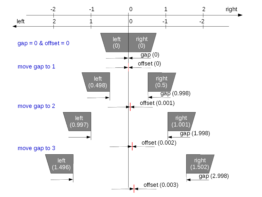
This sketch demonstrates the above example where offset drifted by 0.003.
Drift correction enabled
Initial state: gap and offset are at positions 0 (gap totally closed and offset at the nominal position)
Door_lab_1 [1]: wm right left gap offset
                  right           left            gap         offset
User
 High     Not specified  Not specified  Not specified  Not specified
 Current          0.000          0.000          0.000          0.000
 Low      Not specified  Not specified  Not specified  Not specified
Move gap to 1
Door_lab_1 [2]: mv gap 1
The calculation of the physical motors’ positions gives us 0.5 for both right and left (in accordance with the last set offset of 0).
Door_lab_1 [3]: wm right left gap offset
                  right           left            gap         offset
User
 High     Not specified  Not specified  Not specified  Not specified
 Current          0.500          0.498          0.998          0.001
 Low      Not specified  Not specified  Not specified  Not specified
We observe that the gap pseudomotor did not reach the desired position of 1 due to the left’s positioning problem. Left’s position write and read discrepancy of 0.002 causes that the gap reached only 0.998 and that the offset drifted to 0.001.
Move gap to 2
Door_lab_1 [4]: mv gap 2
The calculation of the physical motors’ positions gives us 1 for right and 1 for left (in accordance to the last set offset 0).
Door_lab_1 [5]: wm right left gap offset
                  right           left            gap         offset
User
 High     Not specified  Not specified  Not specified  Not specified
 Current          1.000          0.998          1.998          0.001
 Low      Not specified  Not specified  Not specified  Not specified
We observe that the gap pseudomotor did not reach the desired position of 2 due to the left’s positioning problem. Left’s position write and read discrepancy of 0.002 causes that the gap reached only 1.998 and that the offset drifted again by 0.001 but thanks to the drift correction is maintained at this value.
Move gap to 3
Door_lab_1 [6]: mv gap 3
The calculation of the physical motors’ positions gives us 1.5 for right and 1.5 for left (in accordance to the last set offset of 0).
Door_lab_1 [7]: wm right left gap offset
                  right           left            gap         offset
User
 High     Not specified  Not specified  Not specified  Not specified
 Current          1.500          1.498          2.998          0.001
 Low      Not specified  Not specified  Not specified  Not specified
We observe that the gap pseudomotor did not reach the desired position of 3 due to the left’s positioning problem. Left’s position write and read discrepancy of 0.002 causes that the gap reached only 2.998 and that the offset drifted again by 0.001 but thanks to the drift correction is maintained at this value.
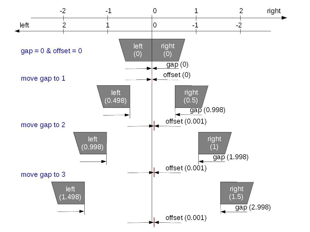
This sketch demonstrates the above example where offset’s drift was corrected.
Footnotes
| [1] | We would like to thank Dominique Heinis for sharing his expertise in blender. |