Scans
Perhaps the most used type of macro is the scan macros. In general terms, we call scan to a macro that moves one or more motors and acquires data along the path of the motor(s).
Note
Sardana provides a Scan Framework for developing scan macros so that the scan macros behave in a consistent way. Unless otherwise specified, the following discussion applies to scan macros based on such framework.
The various scan macros mostly differ in how many motors are moved and the definition of their paths.
Typically, the selection of which data is going to be acquired depends on the active measurement group and is not fixed by the macro itself (although there is no limitation in this sense).
Depending on whether the motors are stopped before acquiring the data or not, we can classify the scan macros in step scans or continuous scans, respectively.
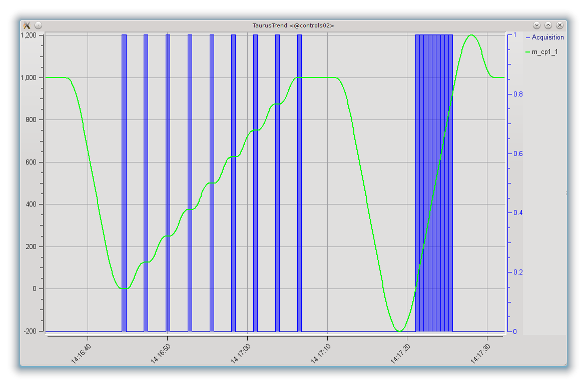
Trend plot showing a step scan (ascan m_cp1_1 0 1000 8 .5)
followed by a continuous scan (ascanc m_cp1_1 0 1000 .5).
The line corresponds to the motor position and the blue shaded areas
correspond to the intervals in which the data acquisition took place.
Step scans
In a step scan, the motors are moved to given points, and once they reach each point they stop. Then, one or more channels are acquired for a certain amount of time, and only when the data acquisition is finished, the motors proceed to the next point.
In this way, the position associated to a data readout is well known and does not change during the acquisition time.
Some examples of step scan macros are:
ascan,
a2scan, …
dscan,
d2scan, …
mesh.
Continuous scans
In a continuous scan, the motors are not stopped for acquisition, which therefore takes place while the motors are moving. The most common reason for using this type of scan is optimizing the acquisition time by not having to wait for motors to accelerate and decelerate between acquisitions.
The continuous scans introduce some constraints and issues that should be considered.
- If a continuous scan involves moving more than one motor simultaneously
(as it is done, e.g. in
a2scan), then the movements of the motors should be synchronized so that they all start their path at the same time and finish it at the same time. - If motors do not maintain a constant velocity along the path of their movement, the trajectories followed when using more than one motor may not be linear.
- While in step scans it is possible to scan two pseudo-motors that access the same physical motors (e.g. the gap and offset of a slit, being both pseudo-motors accessing the same physical motors attached to each blade of the slit), in a continuous scan the motions cannot be decoupled in a synchronized way.
- Backslash correction is incompatible with continuous scans, so you should keep in mind that continuous scans should only be done in the backslash-free direction of the motor (typically, by convention the positive one for a physical motor).
In order to address the first two issues, the scan framework attempts the following:
- If the motors support changing their velocity, Sardana will adjust the velocities of the motors so that they all start and finish the required path simultaneously. For motors that specify a range of allowed velocities, this range will be used (for motors that do not specify a maximum allowed velocity, the current “top velocity” will be assumed to be the maximum)
- For motors that can maintain a constant velocity after an acceleration phase (this is the case for most physical motors), Sardana will transparently extend the user-given path both at the beginning and the end in order to allow for the motors to move at constant velocity along all the user defined path (i.e., the motors are allowed time and room to accelerate before reaching the start of the path and to decelerate after the end of the nominal path selected by the user)
These two actions can be seen in the following plot of the positions of the two
motors involved in a a2scanc.
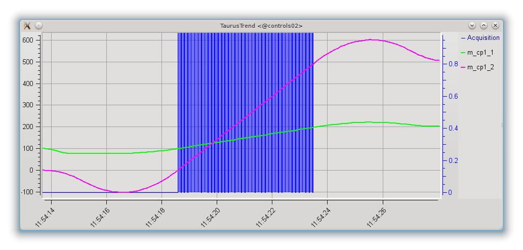
Trend plot showing a two-motor continuous scan
(a2scanc m_cp1_1 100 200 m_cp1_2 0 500 .1).
The lines correspond to the motor positions and the blue shaded areas correspond to the intervals in
which the data acquisition took place.
Both motors are capable of same velocity and acceleration, but since the required scan path for m_cp1_1 is shorter than that for m_cp1_2, its top velocity has been adjusted (gentler slope for m_cp1_1) so that both motors go through the user-requested start and stop positions simultaneously.
The same figure also shows how the paths for both motors have been automatically (and transparently, for the user) extended to guarantee that the user defined path is followed at constant velocity and that the data acquisition takes place also while the motors are running at constant velocity.
The synchronization of movement and acquisition can be done via hardware or via software. Currently Sardana provides two different interfaces for continuous scans. They can be easily differentiated by the scan name suffix:
- c - allows only software synchronization
- ct - allows both software and hardware synchronization (introduced with SEP6)
In the c type of scans, in order to optimize the acquisition time, Sardana
attempts to perform as many acquisitions as allowed during the scan time. Due
to the uncertainty in the delay times involved, it is not possible to know
beforehand how many acquisitions will be completed. In other words, the number
of acquired points along a continuous scan is not fixed (but it is guaranteed
to be as large as possible). Some examples of continuous scan macros are:
ascanc,
a2scanc, …
dscanc,
d2scanc, …
meshc.
In the ct type of scans, Sardana perform the exact number of acquisitions
selected by the user by the means of hardware or software synchronization
configurable on the
measurement group level.
The software synchronized channels may not follow the synchronization pace and
some acquisitions may need to be skipped. In order to mitigate this risk an
extra latency time can be spend in between the scan points. Another possibility
is to enable data interpolation in order to fill the gaps in the scan records.
Some examples of continuous scan macros are:
ascanct,
a2scanct, …
dscanct,
d2scanct, …
At the time of writing the ct types of continuous scans
still do not support acquiring neither of: 1D,
2D, Pseudo Counter
nor external attributes e.g. Tango however their support is planned in the
near future.
Note
The creation of two different types of continuous scans is just the result of the iterative development of the Scan Framework. Ideally they will merge into one based on the ct approach. This process may require backwards incompatible changes (up to and including removal of the affected scan macros) if deemed necessary by the core developers.
Configuration
Scans are highly configurable using the environment variables (on how to use environment variables see environment related macros in Standard macro catalog).
Following variables are supported:
- ApplyExtrapolation
Enable/disable the extrapolation method to fill the missing parts of the very first scan records in case the software synchronized acquisition could not follow the pace. Can be used only with the continuous acquisition macros e.g. ct type of continuous scans or timescan. Its value is of boolean type.
Note
The ApplyExtrapolation environment variable has been included in Sardana on a provisional basis. Backwards incompatible changes (up to and including removal of this variable) may occur if deemed necessary by the core developers.
- ApplyInterpolation
Enable/disable the zero order hold a.k.a. “constant interpolation” method to fill the missing parts of the scan records in case the software synchronized acquisition could not follow the pace. Can be used only with the continuous acquisition macros ct type of continuous scans or timescan. Its value is of boolean type.
Note
The ApplyInterpolation environment variable has been included in Sardana on a provisional basis with SEP6. Backwards incompatible changes (up to and including removal of this variable) may occur if deemed necessary by the core developers.
- DirectoryMap
In case that the server and the client do not run on the same host, the scan data may be easily shared between them using the NFS. Since some of the tools e.g. showscan rely on the scan data file the DirectoryMap may help in overcoming the shared directory naming issues between the hosts.
Its value is a dictionary with keys pointing to the server side directory and values to the client side directory/ies (string or list of strings).
- ScanDir
- Its value is of string type and indicates an absolute path to the directory where scan data will be stored.
- ScanFile
- Its value may be either of type string or of list of strings. In the second case data will be duplicated in multiple files (different file formats may be used). Recorder class is implicitly selected based on the file extension. For example “myexperiment.spec” will by default store data in SPEC compatible format (see more about the extension to recorder map in Writing recorders).
- ScanRecorder
Its value may be either of type string or of list of strings. If ScanRecorder variable is defined, it explicitly indicates which recorder class should be used and for which file defined by ScanFile (based on the order).
Example 1:
ScanFile = myexperiment.spec
ScanRecorder = FIO_FileRecorder
FIO_FileRecorder will write myexperiment.spec file.
Example 2:
ScanFile = myexperiment.spec, myexperiment.h5
ScanRecorder = FIO_FileRecorder
FIO_FileRecorder will write myexperiment.spec file and NXscan_FileRecorder will write the myexpriment.h5. The selection of the second recorder is based on the extension.
- SharedMemory
- Its value is of string type and it indicates which shared memory recorder should be used during the scan e.g. “sps” will use SPSRecorder (sps Python module must be installed on the PC where the MacroServer runs).
See also
For more information about the implementation details of the scan macros in Sardana, see scan framework